Surface acoustic wave device, duplexer, and communications equipment

a surface acoustic wave and duplexer technology, applied in the direction of piezoelectric/electrostrictive/magnetostrictive devices, electrical apparatus, impedence networks, etc., can solve the problem of increasing the insertion loss of the saw device, the request in a market to achieve miniaturization cannot be satisfied, and the loss of the duplexer is high in the technology disclosed, etc. problem, to achieve the effect of reducing the attenuation of the transmission signal

Active Publication Date: 2006-08-24
KYOCERA CORP
View PDF8 Cites 5 Cited by
  • Summary
  • Abstract
  • Description
  • Claims
  • Application Information

AI Technical Summary

Benefits of technology

[0030] According to this configuration, a parasitic capacitance required for out-of-band attenuation generated in the receiving SAW resonator can be increased, so that higher attenuation characteristics can be more easily obtained.
[0031] When the ladder-type transmission SAW device and the ladder-type SAW device for receiving are respectively formed on the main surfaces of the different piezoelectric substrates, coupling between the ladder-type transmission SAW device and the ladder-type SAW device for receiving by a SAW that propagates on the surface of the piezoelectric substrate or a bulk wave that propagates within the piezoelectric substrate can be eliminated. Therefore, a SAW device, which can be suitably employed as a duplexer, superior in isolation characteristics can be obtained.
[0032] If the SAW device according to the present invention is used as a duplexer, the attenuation of a transmission signal is reduced, so that communications equipment having low power consumption can be configured. Since a transmission signal in the communications equipment is not returned as a receiving signal, the communications equipment can carry out high-quality communication having little receiving noise.

Problems solved by technology

As a result, the insertion loss of the SAW device is increased.
Since the ladder-type transmission SAW device in the duplexer is required to have a lower loss in a transmission frequency band, the duplexer has a high loss in the technology disclosed in JP 2001-308671 A.
Therefore, a request in a market to achieve miniaturization cannot be satisfied.

Method used


Image

  • Surface acoustic wave device, duplexer, and communications equipment
  • Surface acoustic wave device, duplexer, and communications equipment
  • Surface acoustic wave device, duplexer, and communications equipment

Examples


examples

[0085] Examples of manufacturing a SAW device according to the present invention will be described.

[0086] Lithium tantalate (LiTaO3) was used for a piezoelectric substrate, a Ti thin film having a thickness of 6 nm was formed on its main surface, an Al—Cu thin film having a thickness of 130 nm was formed thereon, and three Ti thin films and three Al—Cu thin films were alternately laminated to form a Ti / Al—Cu laminated film of six layers in total.

[0087] A photoresist was then applied to a thickness of approximately 0.5 μm by a resist application device.

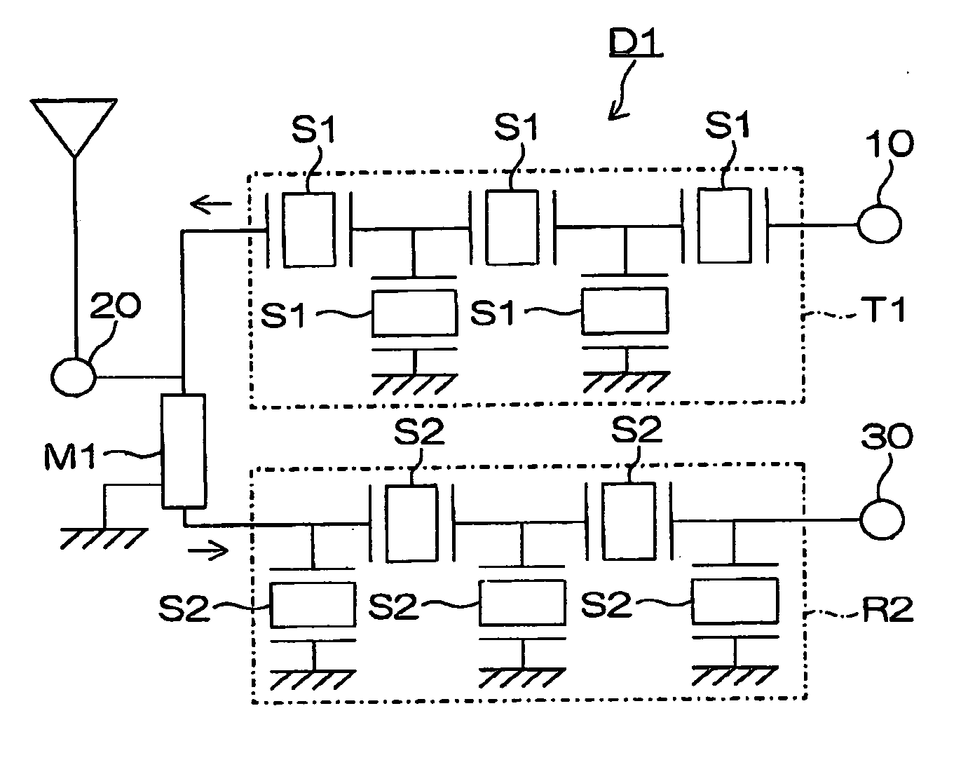
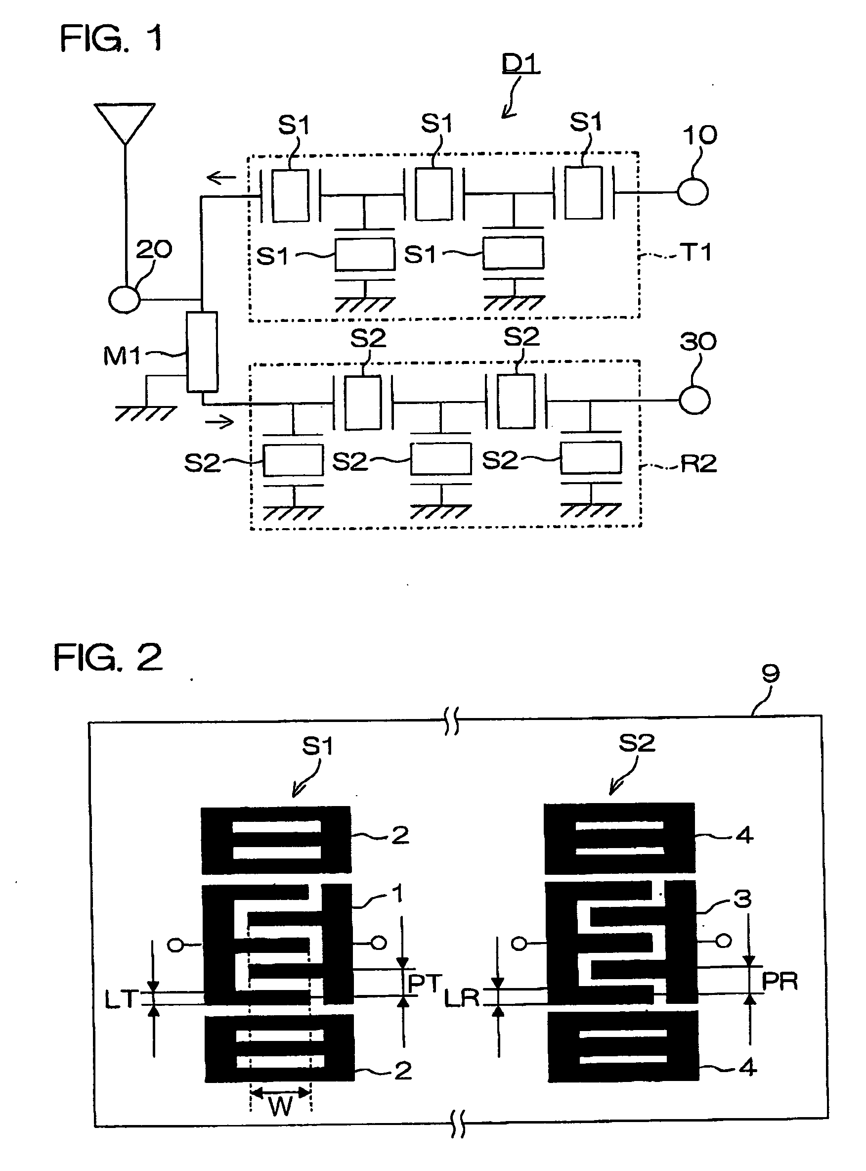
[0088] A photoresist pattern was formed stepper in such a manner that the line width ratio (LT / PT) of IDT electrode fingers in a SAW resonator S1 in a ladder-type SAW device T1 for transmission shown in FIG. 2 was lower than the line width ratio (LR / PR) of IDT electrode fingers in a SAW resonator S2 in a ladder-type SAW device R2 for receiving shown in FIG. 2.

[0089] The photoresist in an unnecessary portion was then dissolved using...


PUM


Abstract

A SAW device D1 according to the present invention comprises a ladder-type SAW device T1 for transmission and a ladder-type SAW device R2 for receiving on a main surface of a piezoelectric substrate. The ratio (LT/PT) of the width LT of electrode fingers to the pitch PT between the electrode fingers in a SAW resonator S1 in the ladder-type SAW device T1 for transmission is made lower than the ratio (LR/PR) of the width LR of electrode fingers to the pitch PR between the electrode fingers in a SAW resonator S2 in the ladder-type SAW device R2 for receiving. As a result, the SAW device D1 has a low loss within a band and has steep attenuation characteristics outside the band, and is miniaturized.

Description

BACKGROUND OF THE INVENTION [0001] 1. Field of the Invention [0002] The present invention relates to a surface acoustic wave device (hereinafter referred to as a “SAW device”), a duplexer comprising the SAW device, and a communications equipment carrying the duplexer [0003] 2. Description of Related Art [0004] In recent years, as devices used for equipment utilizing radio waves, e.g., filters, delay lines, oscillators, etc. in communications equipment, SAW devices having features of being small in size and light in weight and having a steep cutoff performance as the filters have been frequently employed. [0005] The SAW devices have been frequently used for filters in RF stages and IF stages of cellular phones, for example. The SAW devices have been also frequently used for duplexers that are circuits just below antennas. [0006] The SAW devices are required to have low losses, have high attenuation characteristics outside pass bands, and have wide pass bands. [0007]FIGS. 8 and 9 are ...

Claims


Application Information

Patent Timeline
Patent Type & Authority Applications(United States)
IPC IPC(8): H03H9/72H03H9/64
CPCH03H9/725H03H9/72
Inventor ITO, MOTOKI
Owner KYOCERA CORP
Why Eureka
Try Eureka