Method and apparatus for separating sheet glass

a technology of sheet glass and separation method, applied in the field of sheet glass separation, can solve the problems of fine glass chips, flaws on the glass surface, and difficulty in peeling glass chips in the production line of sheet glass, and achieve the effects of improving edge strength, excellent linearity or directivity, and high quality

Inactive Publication Date: 2006-08-31
ASAHI GLASS CO LTD
View PDF9 Cites 40 Cited by
  • Summary
  • Abstract
  • Description
  • Claims
  • Application Information

AI Technical Summary

Benefits of technology

[0027] In accordance with a method for separating sheet glass, according to the present invention, a minute crack of a score, which has been engraved in the vicinity of the separation initiation point, can be caused to propagate along the imaginary line of separation to form a crack required for separation by a combination of heating by the combustion flame of the heating burner and localized cooling by the mist.
[0028] In the heating and cooling operations, thick sheet glass or sheet glass having a great residual stress can be heated without being fused or subjected to the occurrence of a fracture by imbalanced thermal stresses, since it is possible to heat a relatively wide range of a glass surface to a heating temperature and in a heating width by the heating burner. Additionally, even if sheet glass has a warp or a buckle, the sheet glass can have a targeted portion substantially uniformly heated since the heating burner has less influence on the heating temperature than lasers when there are variations in the distance between the heating burner and a glass surface to be heated.
[0029] By this arrangement, it is possible to obtain separated surfaces having high quality and excellent linearity or directivity and to improve edge strength since even sheet glass having a relatively great thickness, or sheet glass having a warp or a buckle, such as ribbon-shaped sheet glass formed by a float glass process, can be easily and stably separated without producing glass chips. The separated surfaces having high quality mean that the number of minute flaws caused on the separated surfaces is small. One of the causes of glass fracture is the presence of such a flaw. The separated surfaces with the pres...

Problems solved by technology

Glass chips that are formed in a production line for sheet glass have a tendency to be difficult to peel away once the glass chips adhered on a glass surface.
Such glass chips cause the occurrence of flaws on a glass surface when the adjacent glass sheets are rubbed each other with the glass chips sandwiched therebetween during storage or transportation of the stacked glass sheets.
When the line of separation 13 is scored by the cutter wheel 17, a glass surface portion of the vertical crack 14 is scooped out in a channel shape, which results in the formation of a mark of line of separation in a brush shape on surface...

Method used


Image

  • Method and apparatus for separating sheet glass
  • Method and apparatus for separating sheet glass
  • Method and apparatus for separating sheet glass

Examples


example

Example 1

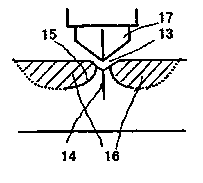
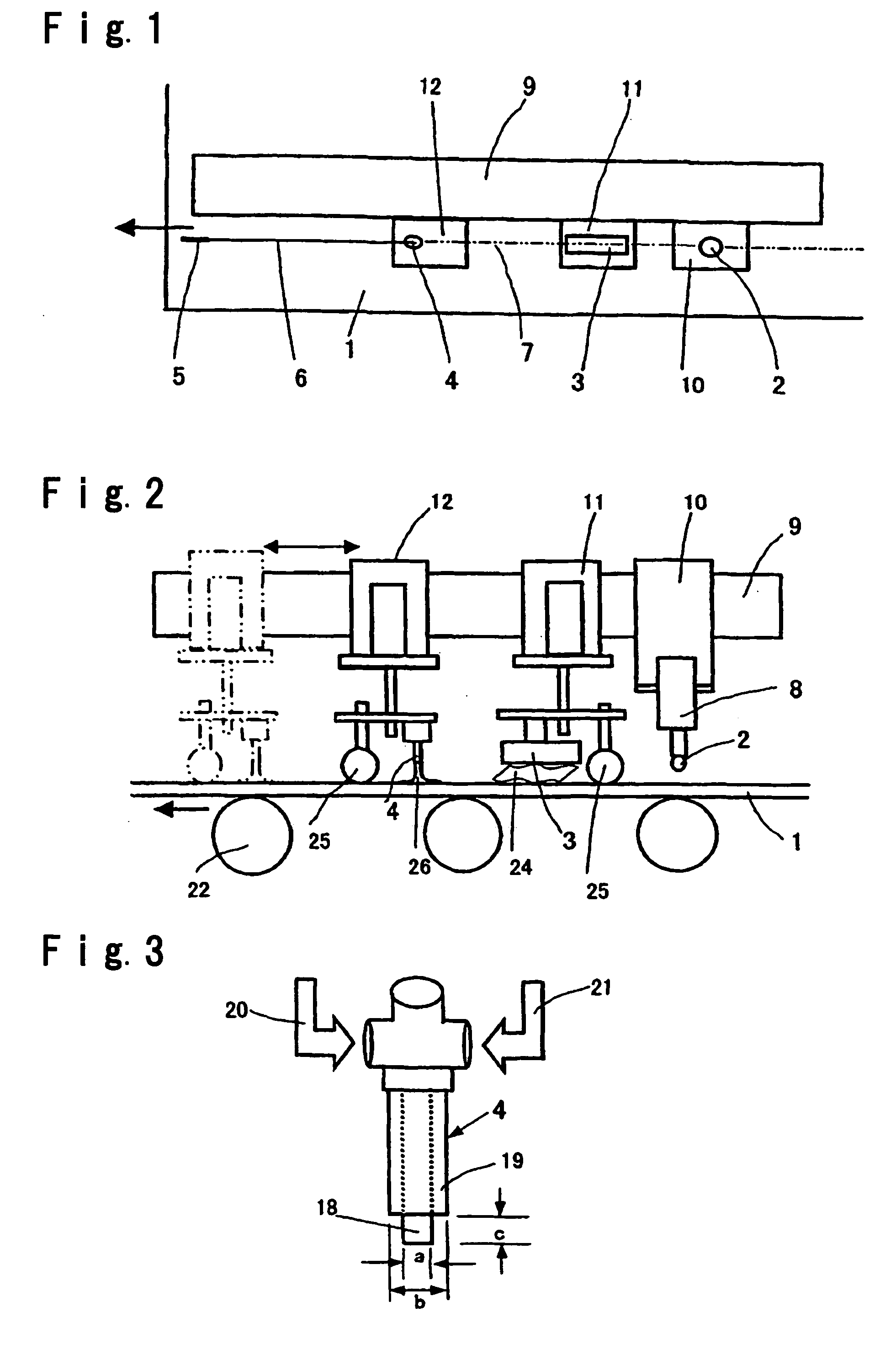
[0083] In the separating apparatus shown in FIG. 1, a diamond wheel was employed to engrave a score having a depth of 100 μm and a length of 7 mm at the separation initiation point of each of glass sheets having thicknesses of 1.8 mm, 3.5 mm, 6 mm, 12 mm and 19 mm under the same score forming conditions as one another. After each of the glass sheets was heated at a portion with the imaginary line of separation set therein by the burner, the heated portion was locally cooled along the imaginary line of separation by the cooling nozzle to form a crack. After each of the glass sheets was bent and separated along the crack, it was visually checked out how the crack was formed and whether glass chips has been produced after the bending and separating operation or not. According to the principle of leverage, each of the glass sheets was bent and separated into smaller sheets by pressing both sides of the crack from upward in such a state that each of the glass sheet was supporte...

example 2

[0088] In the separating apparatus shown in FIG. 1, a diamond wheel is employed to engrave a score having a depth of 100 μm and a length of 7 mm at the separation initiation point of each of glass sheets having thicknesses of 3.5 mm and 5 mm under the same score forming conditions. After each of the glass sheets was heated at a portion with the imaginary line of separation set therein by the burner, the heated portion was locally cooled along the imaginary line of separation by the cooling nozzle to propagate a crack (having the same cooling conditions as Example 1). In such operations, the distance L between the burner and the cooling nozzle was modified in a range of from 180 to 380 mm for the glass sheet having a thickness of 3.5 mm and in a range of from 180 to 460 mm for the glass sheet having a thickness of 5 mm in order to investigate the relationship between L and the depth of a formed crack. The results of the investigation are shown in Table 3. The heating conditions of th...

example 3

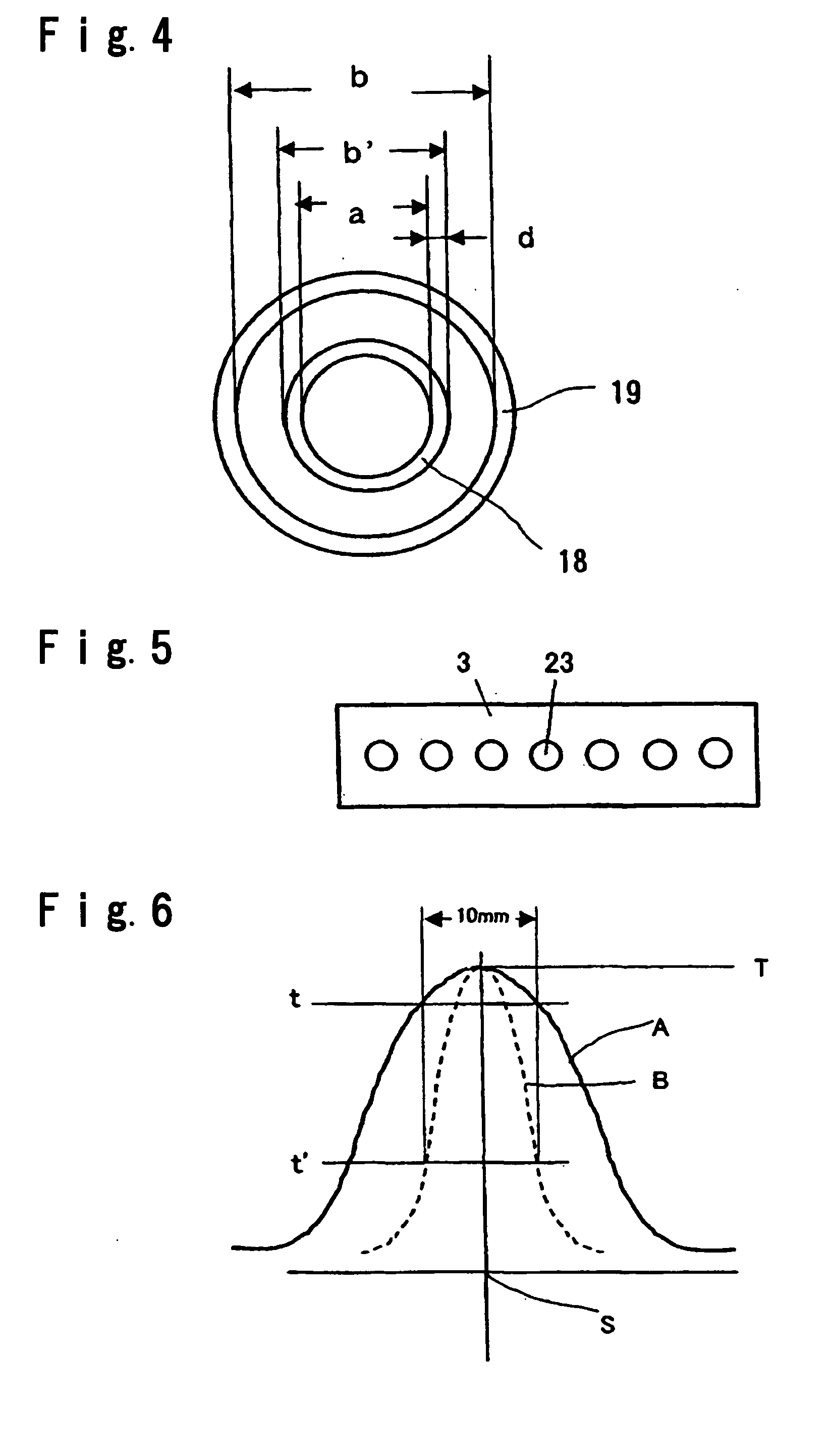
[0091] In the separating apparatus shown in FIG. 1 a crack required for separation was formed in a longitudinal direction in each of glass sheets (100 cm in length×100 cm in width×3.5 mm in thickness) with the score forming conditions for the cutter and the heating conditions for the heating burner (gas / O2: 300 / 280 (Nl / h)) being fixed, with the locally cooling conditions for the cooling nozzles modified with respect to only the projection amount of the liquid-ejecting port to modify the cooling width, and with the other conditions being the same as one another. After that, a bending moment was applied to the cracked portion of each of the glass sheets to bend and separate each of the glass sheets into separate sheets, and the linearity of the separated portion of each of the glass sheets was checked out. The conveying speed for the glass sheets was set at 900 m / h.

[0092] In the case stated above, the diamond wheel is used to engrave each of the scores in a depth of 100 μm and at a l...


PUM


Abstract

In separation of sheet glass by making use of thermal strain, separated surfaces can be obtained to avoid the occurrence of glass chips and to have excellent linearity even in relatively thick sheet glass. After a score, which serves as a crack initiation point is engraved at a separation initiation point in sheet glass, the sheet glass is heated along an imaginary line of by a heating burner; the heated portion of the sheet glass with the imaginary line of separation set therein is locally cooled by a mist, which is produced by a cooling nozzle comprising a liquid-ejecting port disposed at a central portion thereof and a gas-ejecting port disposed around an outer periphery of the liquid-ejecting port, the liquid-ejecting port projecting farther than the gas-ejecting port; and a minute crack of the score is caused to propagate along the imaginary line of separation to form a crack required for separation of the sheet glass.

Description

TECHNICAL FIELD [0001] The present invention relates to separation of sheet glass, and more particularly to a method and an apparatus wherein after sheet glass is heated along an imaginary line of separation by a combustion flame of a heating burner, the heated portion of the sheet glass with the imaginary line of separation set therein is locally cooled to cause a crack necessary for separation to continuously propagate in the sheet glass, and the sheet glass is bent and separated into separate sheets. BACKGROUND ART [0002] As major separating methods for sheet glass, there have been known a method employing a cutter, such as a diamond wheel or a carbide wheel, and a method making use of thermal strain. The former method is one wherein a line of separation is scored in sheet glass by a cutter, and the sheet glass is bent and separated into separate sheets along the line of separation (hereinbelow, referred to as separation by a cutter), and which has been most commonly performed. H...

Claims


Application Information

Patent Timeline
IPC IPC(8): B26F3/00B27M1/00B27M1/02B27M1/06C03B33/023C03B33/09
CPCC03B33/0235C03B33/09Y10T225/12Y02P40/57C03B33/03C03B33/10
Inventor KATAOKA, YASUYOSHITAKAHASHI, TOMIO
Owner ASAHI GLASS CO LTD
Why Eureka
Try Eureka