Plasma deposition apparatus and method

a technology of thin film and deposition apparatus, which is applied in the direction of vacuum evaporation coating, electrolysis components, coatings, etc., can solve the problems of low ionization degree of gas, electrodes are apt to be damaged after repeated use, and plasma is only suitable for use, so as to improve the thickness uniformity of thin film

Inactive Publication Date: 2006-09-07
HON HAI PRECISION IND CO LTD
View PDF7 Cites 25 Cited by
  • Summary
  • Abstract
  • Description
  • Claims
  • Application Information

AI Technical Summary

Benefits of technology

[0008] In a preferred embodiment, a deposition apparatus includes a reaction chamber, a magnetic device, a microwave source, two sputtering targets and a substrate holder. The reaction chamber includes at least one reaction gas inlet for introducing corresponding at least one reaction gas therethrough and a vacuum system. The reaction chamber has a predetermined plasma generation region. The magnetic device is configured for producing a magnetic field around the plasma generation region. The two sputtering targets are disposed at opposite sides of the plasma generation region and the sputtering targets facing each other. The substrate holder is for securing a work piece thereon. The frequency of the microwave is matched with the strength of the magnetic field and sufficient to cause electron cyclotron resonance (ECR) in the reaction chamber to form plasma. Then the plasma bombard the sputtering targets and sputter the target atoms to deposit on the work piece to form a thin film. Preferably, the gas pressure of the reaction chamber is in the range from 0.1 to 10 torr. The frequency of the microwave is set about 2.45 GHz and the matched magnetic strength is set about 875 Gauss. The plasma density reaches to the range between 5×1010 cm−3 and 9×1012 cm−3. The substrate holder is rotatable along a central axis associated therewith to improve the thickness uniformity of the thin film.

Problems solved by technology

However, the ionization degree of the gas is low.
The electrodes are apt to be damaged after repeated use.
However, the resultant plasma is only suitable for use in a chemical vapor deposition process.
The problem of this kind plasma deposition apparatus is that the activated ions have not enough kinetic energy.
As a result, it is not suitable for forming a crystalline thin film.
The problem of this kind plasma deposition apparatus is that the raw sputtering materials are limited to be in a form of gas (such as CH4 and C2H5).
The material having a high melting point, such as metal and metal oxide, cannot be used as the raw materials for forming thin films.
Therefore, The available raw sputtering materials are limited.
Such plasma deposition apparatus can only be suitable for depositing Si, or C thin films.

Method used


Image

  • Plasma deposition apparatus and method
  • Plasma deposition apparatus and method
  • Plasma deposition apparatus and method

Examples


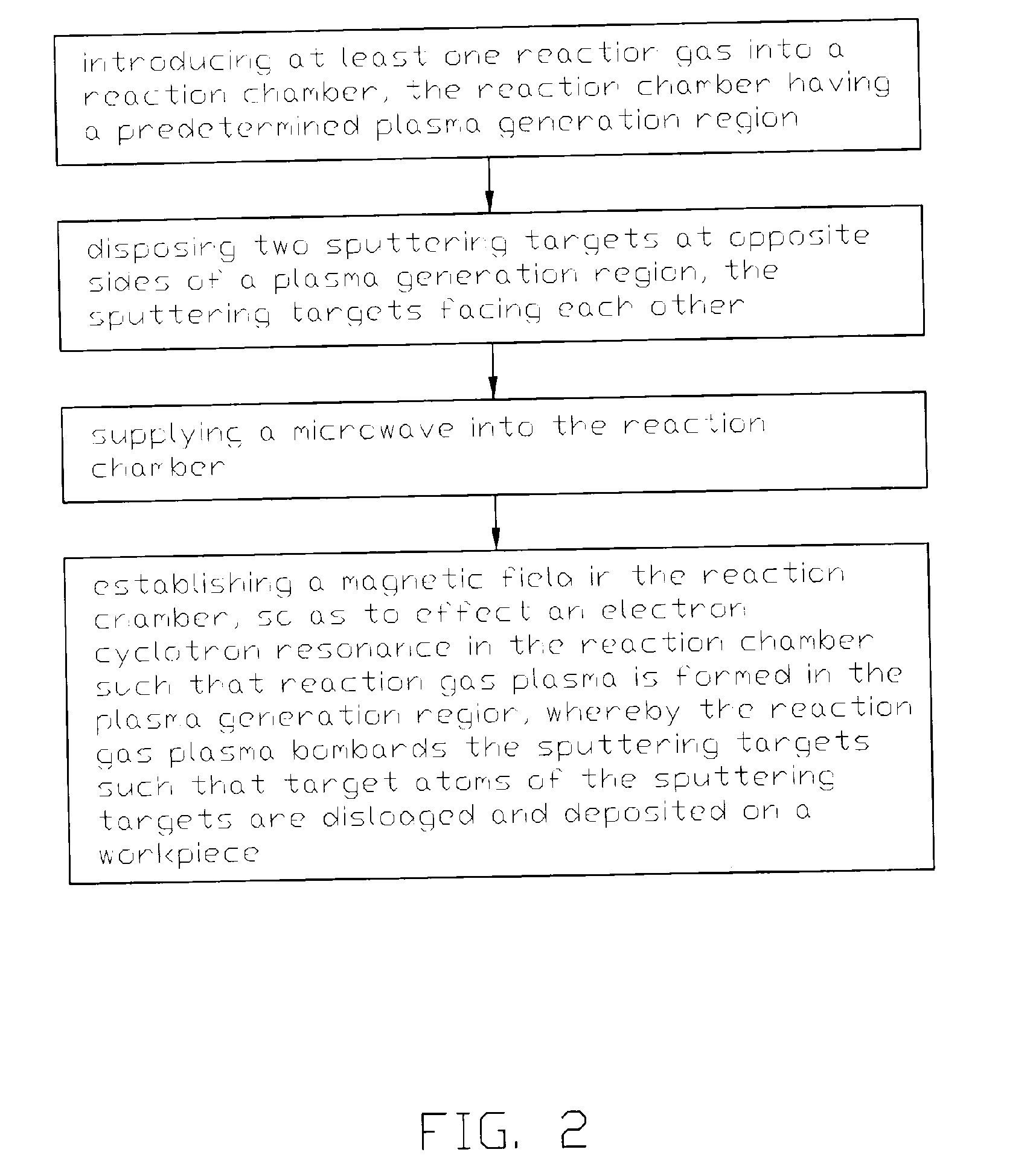
Embodiment Construction

[0017] Reference will now be made to the drawings to describe embodiments of the present invention, in detail.

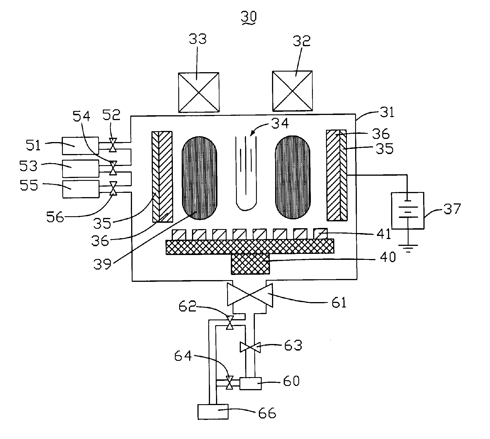
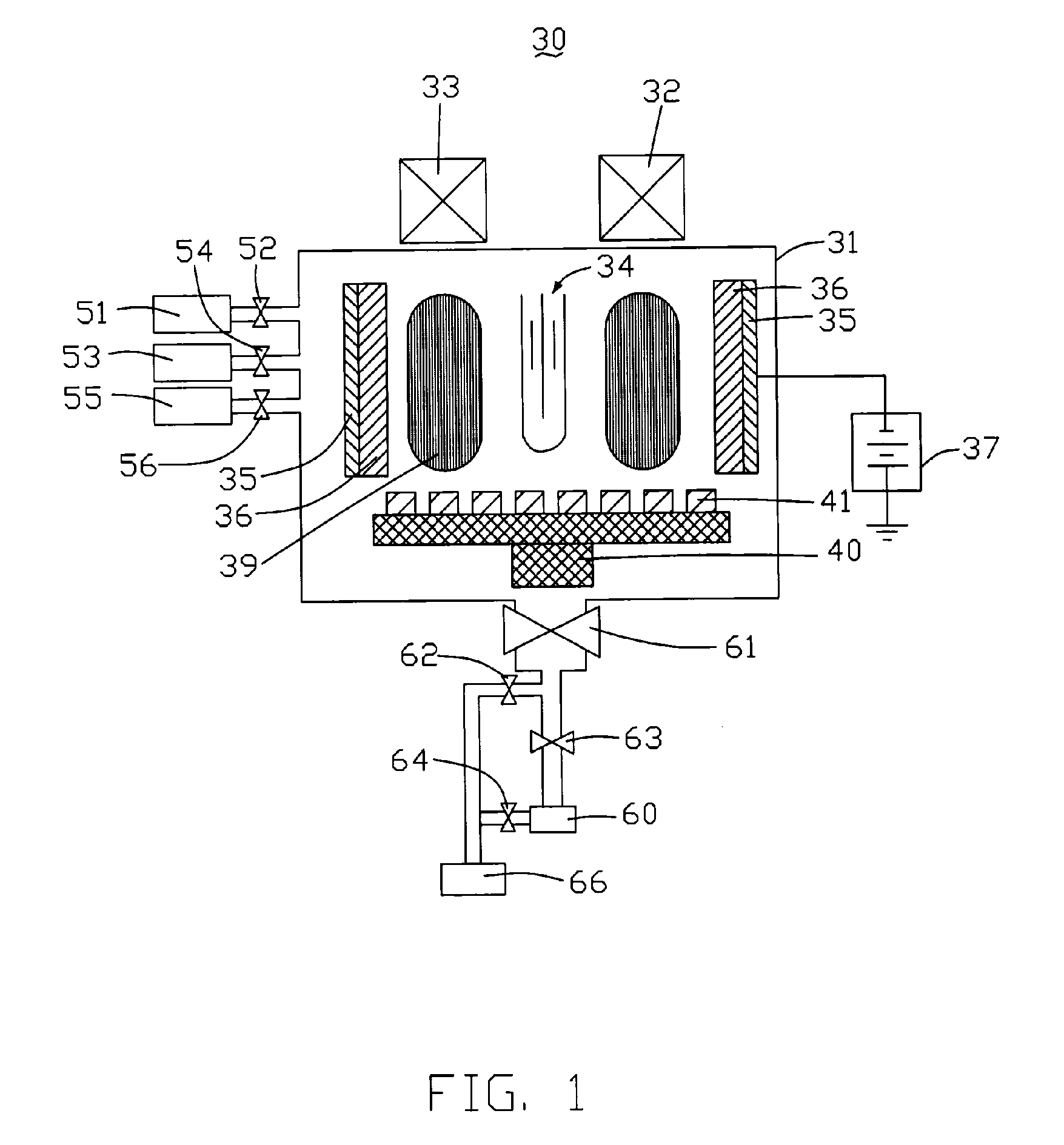
[0018] Referring to FIG. 1, a plasma enhanced deposition apparatus 30 comprises an reaction chamber 31, a plurality of mass flow controllers 52,54,56, a turbo pump 60, a rough pump 66, four valves 61,62,63,64, two magnetic coils 32,33, an antenna 34, two sputtering targets 36, two cathodes 36, a DC power supply 37 and a substrate holder 40.

[0019] The reaction chamber 31 includes a plasma generation region 39 where a dense plasma is generated. A plurality of reaction gas containers 51, 53, 55 is connected to the reaction chamber 31. The mass flow controllers 52,54,56 are for controlling flow rates of the reaction gases. In the illustrated exemplary embodiment, the reaction gas container 51 contains one of Ar, Kr and Xe. The reaction gas container 53 contains a combination of Ar and N2. The reaction gas container 55 contains one of a combination of Ar and H2, a combination o...


PUM

PropertyMeasurementUnit
frequencyaaaaaaaaaa
gas pressureaaaaaaaaaa
pressureaaaaaaaaaa

Abstract

The present invention relates to a plasma deposition apparatus and method for forming a thin film on a work piece (41). The deposition apparatus (30) includes a reaction chamber (31), a magnetic device (32,33), a microwave device, two sputtering targets (36), and a substrate holder (40). The reaction chamber includes at least one reaction gas inlet for introducing corresponding at least one reaction gas therethrough and a vacuum system. The reaction chamber has a predetermined plasma generation region. The magnetic device is configured for producing a magnetic field around the plasma generation region. The two sputtering targets are disposed at opposite sides of the plasma generation region and the sputtering targets facing each other. The substrate holder is for securing a work piece thereon. The microwave is in an enough frequency that matches the strength of the magnetic field for conducting electron cyclotron resonance (ECR) in the position and producing plasma with high density in the reaction chamber. Therefore, ions of the plasma bombard the sputtering targets and sputter the target atoms to deposit on the work piece for forming a thin film.

Description

FIELD OF THE INVENTION [0001] The present invention relates to a thin film deposition apparatus and method, and more specifically, to a plasma deposition apparatus and method which utilize electron cyclotron resonance (ECR) to increase a density of plasma to form a thin film. DESCRIPTION OF RELATED ART [0002] Plasma is the forth state of matter. Plasma is a collection of ionized gas consisting of free electrons and ions. Energy needs to be provided for dislodging electrons from atoms / molecules thereby forming the plasma. The energy can be of various forms: e.g. heat energy, electrical energy, or light energy. The plasma can be used in numerous applications such as thin film deposition, plasma based lighting systems, plasma spray and display systems, etc. [0003] Typical methods for producing low temperature plasma include a direct current glow discharge method, a radio frequency glow discharge method and a microwave discharge method. As regards direct current glow discharge method, a...

Claims


Application Information

Patent Timeline
Patent Type & Authority Applications(United States)
IPC IPC(8): C23C14/00
CPCC23C14/352C23C14/357H01J37/32192H01J37/32678H01J37/3405
Inventor CHEN, GA-LANE
Owner HON HAI PRECISION IND CO LTD
Why Eureka
Try Eureka