

Stereolithography apparatus
- Summary
- Abstract
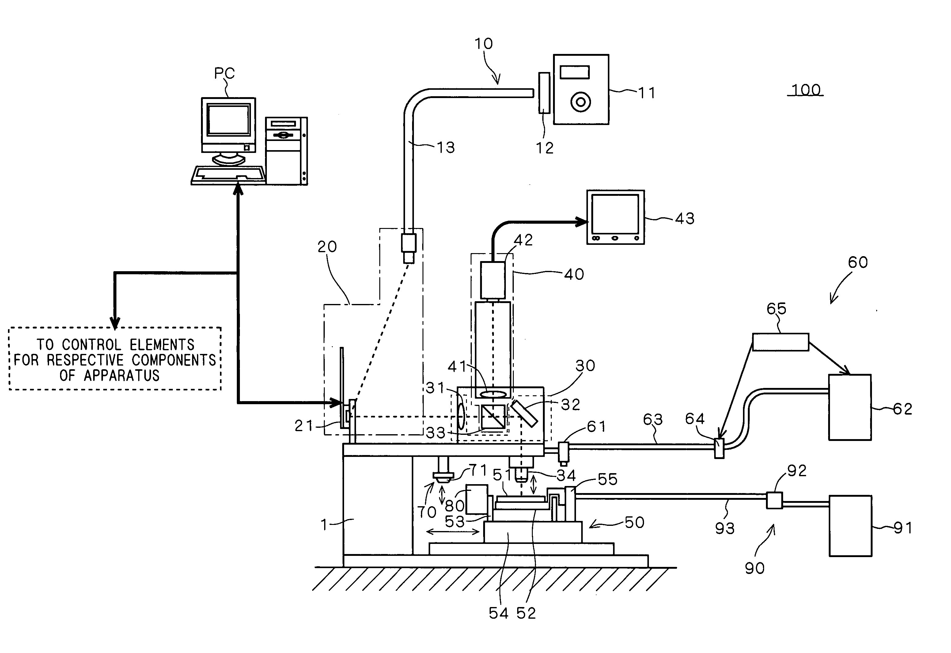
- Description
- Claims
- Application Information
AI Technical Summary
Benefits of technology
Problems solved by technology
Method used
Image

Examples
example
[0071]FIG. 6 shows a SEM (scanning electron microscope) image of model samples created using the stereolithography apparatus 100 according to the above-mentioned preferred embodiment. The modeling was carried out by employing laser light having a wavelength of 405 nm as a light source and using an acrylate resin (having a viscosity of 1500 to 2500 mPa·s at 25° C.) as the photo-curable resin. Each of the model samples is created on a base surface, and has a 26 by 26 μm square bottom surface, a 5 by 5 μm square top portion, and a height of about 70 μm by stacking seven resin layers each having a thickness of about 10 μm. Although not shown in detail, a modeling error relative to design data was about 2 μm or less.
[0072] Thus, a layer thickness of 10 μm and an exposure resolution of 2 μm were attained in the stereolithography apparatus 100 according to the preferred embodiment.
PUM
| Property | Measurement | Unit |
|---|---|---|
| Thickness | aaaaa | aaaaa |
| Thickness | aaaaa | aaaaa |
Abstract
Description
Claims
Application Information