Programming of industrial automation equipment using RFID technology

a technology of industrial automation and rfid, applied in the direction of electrical programme control, program control, electric controller, etc., can solve the problems of prone to errors, loss of volatile memory contents, and loss of existing barcode scanning data, etc., to achieve easy recognition, precise relative orientation, and easy recording data

Inactive Publication Date: 2006-09-07
MASON ROBERT C +1
View PDF13 Cites 65 Cited by
  • Summary
  • Abstract
  • Description
  • Claims
  • Application Information

AI Technical Summary

Benefits of technology

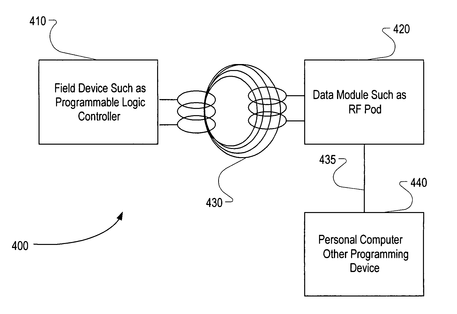
[0017] An appropriate RF connection eliminates the problems of the prior art. An antenna, packaged in a plastic housing for example, can be inserted into a slot or placed on the surface of the equipment to which (or from which) information will be loaded. Thus, there is no direct physical connection, so there is no longer a problem with static electricity, power surges, polarity, or isolation. Data rates for this application can exceed 200 kilobits per second (kbps), so lengthy data transfer times can be avoided. If the power consumption of the RF pod is kept low (at about 25 to 50 milliwatts), then the RF pod can be powered by an RF field from the field device (e.g. the PLC), or by communication port power from the personal computer (PC) that is being used to program the programmable control equipment. The RF Pod can be as simple as an antenna, or as complex as a complete RFID reader / writer including an antenna.
[0019] In conjunction with this scenario, an RFID device can also be used as a security key. A given piece of industrial control equipment can be programmed to operate only if a module containing specific permission codes is in close proximity to its antenna area. Quite lengthy permission codes can be programmed into a piece of industrial control equipment, in excess of a thousand bytes, which makes it effectively impossible to break the security code.
[0021] According to one embodiment, this invention is useable with the industrial control equipment in the production of a plurality of products. For example, a line of products may flow through an assembly line, and some of those products may be different from others, thus requiring different assembly techniques. By equipping at least some of the products with RFID tags, these products can be more easily recognized by a programmable logic controller so that, by identifying itself, the product controls how it will be assembled, tested, or processed. In this scenario, there can be one RFID connection, or more than one RFID connection (e.g. an RFID connection from the product to an I / O module and then an RFID connection from the I / O module to a CPU of the PLC). Likewise, such an RFID connection can be used to more easily record data about the product (e.g. serial numbers), which is important for pharmaceutical and other products. This RFID connection improves upon existing barcode scanning, which is prone to error, which requires a very precise relative orientation between a product and a barcode reader, and which severely limits the amount of data that can be communicated. Identifying products by human observation, accompanied by a human / machine interface HMI, is also subject to error, as well as high labor costs. Adapting RFID technology to this problem allows automated alteration of process parameters and / or recipes, based upon the current product flowing through the line. It eliminates operator intervention and possible error in inputting the type of product currently flowing through a line.
[0022] In another embodiment of the invention, a newly added input or output module at least partly controls a PLC, by identifying itself via RFID, and thus the I / O module lets the PLC know how to configure or control the new module. The subsequent interaction between PLC and I / O module can be either by traditional wired connection, or by wireless connection. Using this RFID technique for identification purposes also allows a user to more easily maintain or upgrade a system by allowing automatic or semi-automatic configuration (or attempted configuration) of new modules added to the system.
[0023] Since RFID relies on contactless electromagnetic coupling, no direct connections are needed to connect two pieces of equipment. Insulating barriers, so long as they are non-metallic, are no impediment to the electromagnetic signals. Thus, two independent circuits may communicate by means of antenna-to-antenna coupling through an insulating barrier. The presence of an insulating barrier eliminates concerns about routing and separation. A secondary benefit of RF coupling is that the data exchange connection has no sensitivity to the polarity of the signals. The signals cannot be connected incorrectly by an installer or user; the antennas either couple or they do not. Thus, it is not only possible, but also highly advantageous, to achieve galvanic isolation of industrial control equipment using RF proximity coupling.

Problems solved by technology

In a traditional system, making this type of change would involve physically changing the wiring between the devices, which is typically a costly and time-consuming endeavor.
In addition, as the installation goes through its service life, its configuration is often changed, necessitating additional programming.
Since the operating voltage comes from the RF field, the contents of a volatile memory are lost when the field is not present.
Existing barcode scanning is prone to error and requires a very precise relative orientation between the product and a barcode reader.
Likewise, identifying products by human observation, accompanied by a human / machine interface (HMI), is also subject to error, as well as high labor costs.
Furthermore, many industrial control installations must face the problem of isolating one circuit or equipment from another, while still allowing communication between them.

Method used


Image

  • Programming of industrial automation equipment using RFID technology
  • Programming of industrial automation equipment using RFID technology
  • Programming of industrial automation equipment using RFID technology

Examples


Embodiment Construction

[0031] Unlike traditional radio methods, infrared methods would not be at all comparable to the technique of the present invention because infrared is limited by line-of-sight issues as well as performance problems caused by the often-dirty industrial environment. At the top level, traditional radio methods significantly differ from the present invention by the frequency of the signals. The lower frequencies of traditional radio require large antennas that are difficult to fit into electronic packaging. RFID antennas, by comparison, take up about 1 square inch of printed wiring board (PWB) area. The nature of the RF field makes it very selective as to what devices will be affected by it. Unless an antenna is placed in close proximity to the transmitter (e.g. only a fraction of a centimeter away) it will not detect or respond to the signal. This makes RFID much more selective than traditional radio transmission.

[0032] As seen in FIG. 4, a system 400 includes the field device which m...


PUM


Abstract

A system, device, and method are disclosed for wirelessly coupling a controlling device to a programmable industrial control equipment such as a programmable logic controller (PLC). The controlling device may, for example, be a personal computer used for programming the PLC. The system includes a radio frequency identification (RFID) unit located at one end of this wireless connection, and also includes at least one antenna at the other end, for communicating with the RFID unit. The RFID unit acts as an intermediary for communication between the programmable industrial control equipment and the controlling device. In case a product in a production line, or a newly added input / output module, provides information that controls a PLC, this control is enhanced by the RFID connection.

Description

TECHNICAL FIELD [0001] The present invention relates to Radio Frequency Identification (RFID) technology, and more particularly to RFID technology used for programming, configuring, or otherwise controlling devices such as programmable logic controllers. BACKGROUND OF THE INVENTION [0002] A programmable logic controller, also called a programmable controller, is a computer-type device used to control equipment in an industrial facility. The kinds of equipment that PLCs can control are as varied as industrial facilities themselves. Conveyor systems, food processing machinery, auto assembly lines are just some examples of instances where there is probably a PLC in control. In a traditional industrial control system, all control devices were wired directly to the controlled device. In a PLC system, however, the PLC replaces the wiring between the devices. Thus, instead of being wired directly to each other, all field devices are wired to the PLC. Then, the control program inside the PL...

Claims


Application Information

Patent Timeline
Patent Type & Authority Applications(United States)
IPC IPC(8): G05B11/01G05B19/18G05B19/42
CPCG05B19/054G05B19/056G05B2219/13167G05B2219/15117
Inventor MASON, ROBERT C.NAISMITH, RONALD H.
Owner MASON ROBERT C
Why Eureka
Try Eureka