Hydrogen supply device and hydrogen supplying method

a technology of hydrogen supply device and hydrogen supply method, which is applied in the direction of hydrogen/synthetic gas production, hydrogen/jet propulsion mounting, internal combustion mounting, etc., can solve the problems of hydrogen being difficult to handle hydrogen at ordinary temperature, and difficult to be handled in storage and delivery than liquid and solid materials. , the effect of combustible hydrogen

Inactive Publication Date: 2006-09-14
HITACHI LTD
View PDF9 Cites 55 Cited by
  • Summary
  • Abstract
  • Description
  • Claims
  • Application Information

AI Technical Summary

Benefits of technology

[0052] This invention can provide a high-efficiency hydrogen supply device which stores hydrogen and supplies it to a distributed power supply such as car or home fuel cell.

Problems solved by technology

However, hydrogen which is essential as a fuel is very hard to be handled in delivery, storage, and distribution.
Hydrogen is a gas substance at ordinary temperature and harder to be handled in storage and delivery than liquid and solid materials.
What is worse, hydrogen is combustible and may explode violently when it is mixed up with air at a preset ratio or higher.
However, benzene is an unsaturated hydrocarbon having double bonds of carbons but cyclohexane is a saturated hydrocarbon having no double bond.
However, the above technologies also have problems.
This will reduce the efficiency of power generation.
Such a hydrogen supply device requires a lot of ancillary equipment such as a sprayer, a cylinder, and a cooler and cannot be down-sized.
Further, since an electric heater is used to heat the catalyst, the overall power efficiency of a power generation system connected to a fuel cell will go down.
However, the reaction rate of the catalyst becomes smaller as the temperature goes down and the quantity of the catalyst must be increased to speed up the supply of organic hydride.
This will make the reaction layer greater, requires more expensive hydrogen separating tubes, and pushes up the production cost.

Method used


Image

  • Hydrogen supply device and hydrogen supplying method
  • Hydrogen supply device and hydrogen supplying method
  • Hydrogen supply device and hydrogen supplying method

Examples


embodiment 1

[0126] The catalyst for dehydrogenating organic hydride is made of a metal catalyst and a carrier material. Specifically, this Embodiment shows the result of consideration of carrier materials.

(Carrier Materials)

[0127] The inventors used activated carbons, Al2O3, ZrO2, Nb2O5, V2O5, and SnO2 as carrier materials. Materials except for Al2O3 are commercially available (e.g. fabricated by Kojundo Chemical Lab. Co., Ltd.) and activated carbons are Vulcan (fabricated by Cabot Corp.)

[0128] The inventors prepared Al2O3 by dissolving 20 grams of aluminum isopropoxide (fabricated by Wako Pure Chemical Industries, Ltd.) into 80 grams of hot water at 80° C., titrating nitric acid (5 ml) into the solution to gelate thereof, and drying the gel at 120° C. for 5 hours and then at 450° C. for 2 hours. The inventors prepared composite carrier materials as follows:

[0129] The inventors prepared Al2O3-based composite oxide (2% by weight of Nb2O5—Al2O3 and 2% by weight of ZrO2—Al2O3) by mixing a spe...

embodiment 2

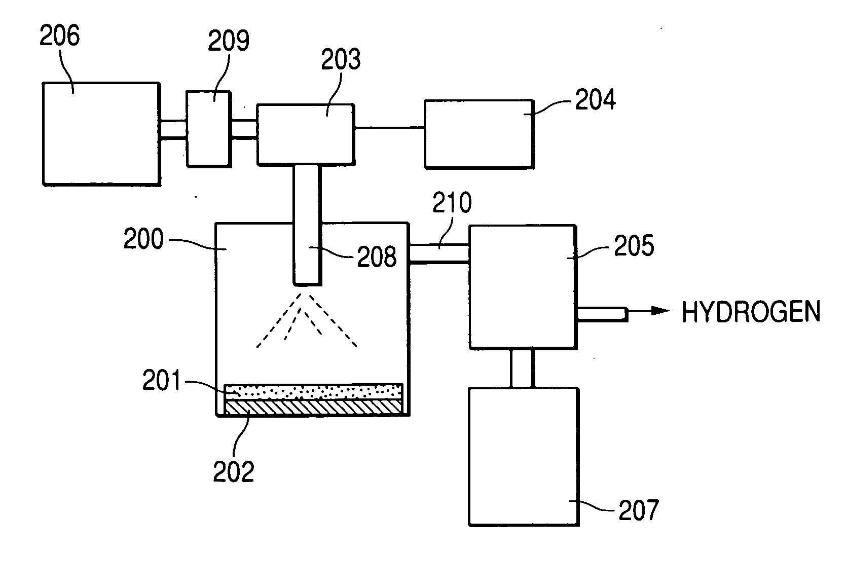
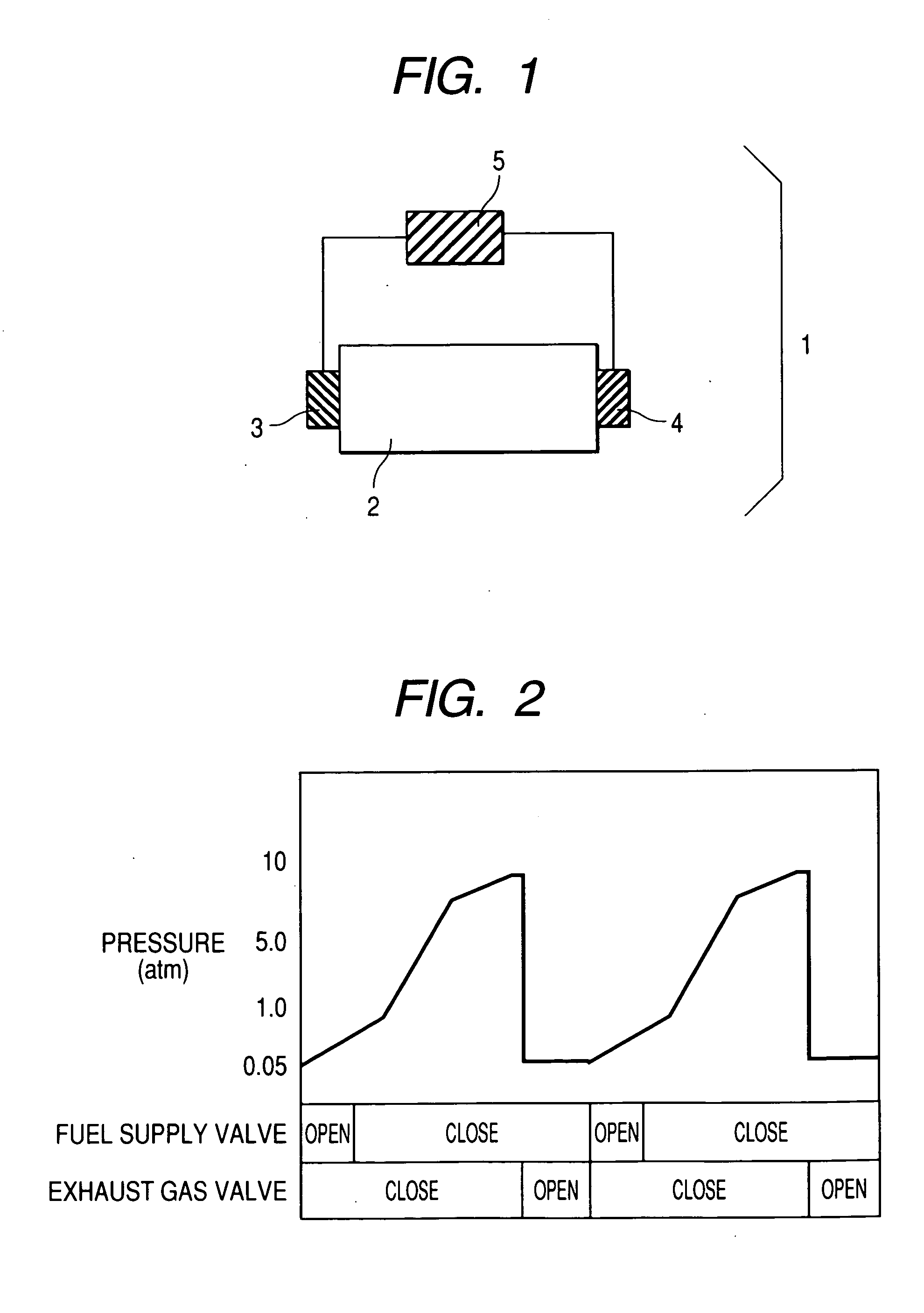
[0136] By this Embodiment, the inventors evaluated the relationships of fuel supply pressure, exhaust pressure, conversion rate, valve control timing by the hydrogen supply device of FIG. 5. The inventors used 0.3 gram of platinum-carrying Nb2O5 catalyst which was prepared for Embodiment 1.

[0137] The evaluation steps comprises filling hydrogen supply device 21 with catalyst powder, mounting valves on inlet and outlet of hydrogen supply device 21, connecting a booster pump to the inlet valve for fuel supply and a vacuum pump to the outlet valve for gas exhaust (wherein these pumps are pressure-controllable), injecting methylcyclohexane at 100 μl / min in the helium gas flow (at 10 ml / min) at 250° C. for dehydrogenation, analyzing the liquid collected from the liquid hydrogen trap by GC-mass (GC-6500 by Simadzu Corp.), measuring the peak area of methylcyclohexane (98) and the peak area of toluene (92), and calculating the conversion rate (from methylcyclohexane to toluene) from the rat...

embodiment 3

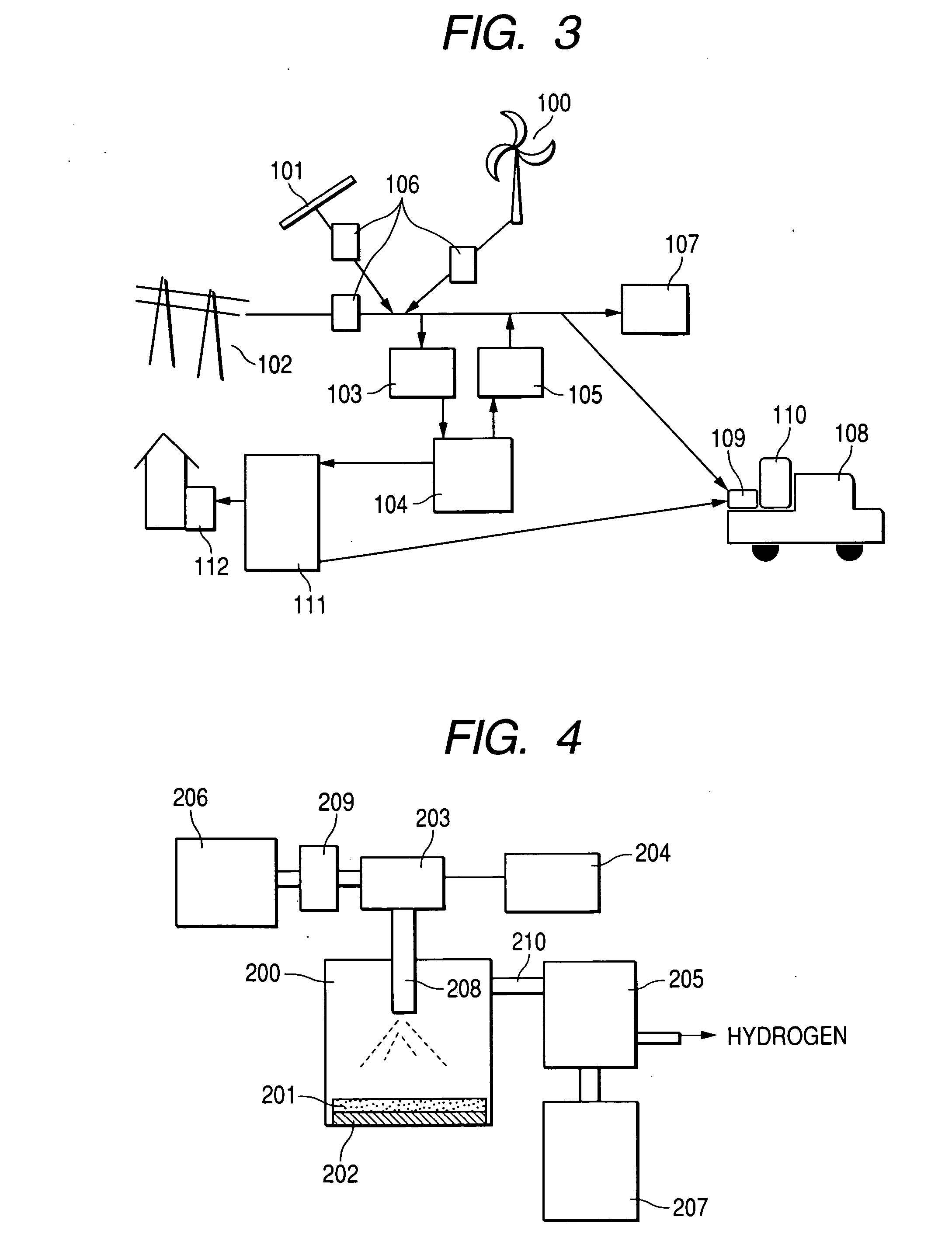
[0142] This embodiment provides a turbine type exhaust device in the exhaust section of the hydrogen supply device.

[0143] The hydrogen supply system of FIG. 5 provides a cooler between the exhaust valve and the exhaust pump to separate gas (hydrogen) and dehydrogenate (liquid). Contrarily, the turbine type separator of FIG. 6 houses a cooler and an exhaust pump in the body to make it smaller and simpler. Further since this type of separator can suck and compress hydrogen gas by the exhaust pump, the hydrogen gas can be stored in an auxiliary tank or the like.

[0144] Next will be explained the turbine type separator of FIG. 6. Turbine type separator 30 mounted on the hydrogen supply system of this invention contains micro turbine 32 with turbine blades 33 in casing 31. The section equivalent to a diffuser of an ordinary micro turbine works as cooler 34 which is equipped with cooling pipe 35 through which a cooling medium flows. The turbine type separator is connected to the outlet o...


PUM

PropertyMeasurementUnit
pressureaaaaaaaaaa
hydrogen generation pressureaaaaaaaaaa

Abstract

A hydrogen supply device which generates hydrogen from hydrogen storing material which chemically stores hydrogen by a catalyst, wherein said device comprises valves on the fuel supply port and the exhaust port, and a valve controller which controls timing to opening and close the valves Fuel supply pressure is 2 to 20 atm. Hydrogen generation pressure is 5 to 300 atm. Exhaust pressure is atmospheric pressure to 0.01 atm.

Description

CLAIM OF PRIORITY [0001] This application claims priority from Japanese application Serial No. 2005-064764, filed on Mar. 9, 2005, the content of which is hereby incorporated by reference into this application. BACKGROUND OF THE INVENTION [0002] 1. Field of the Invention [0003] This invention relates to a hydrogen supply device for supplying hydrogen to automobiles or distributed power supplies such as home fuel cells. [0004] 2. Related Art [0005] From the viewpoint of preventing global warming due to the release of gases such as carbon dioxide, fossil-fuel is going to be outplaced by hydrogen which is expected as the third generation energy source. Further, to promote energy saving by using energy effectively and reducing the release of carbon dioxide, cogeneration of electric power facilities has been attracting public attention. Recently, fuel cell power generation systems which use hydrogen for power generation have been rapidly researched and developed to be used widely in vari...

Claims


Application Information

Patent Timeline
Patent Type & Authority Applications(United States)
IPC IPC(8): B65B3/00H01M8/06B60L11/18B60K5/00B60K15/10
CPCB01D53/04B01D53/0407B01D2256/16B01D2259/40003B01D2259/4566Y02T90/42C01B3/0015C01B3/501C01B2203/041Y02E60/328C01B3/0005Y02E60/32Y02T90/40
Inventor ISHIKAWA, TAKAOKANEMOTO, HIROSHINOUJIMA, MASAFUMIITABASHI, TAKEYUKI
Owner HITACHI LTD
Why Eureka
Try Eureka