Valve lifter

Inactive Publication Date: 2006-09-21
RIKEN CO LTD +1
View PDF2 Cites 15 Cited by
  • Summary
  • Abstract
  • Description
  • Claims
  • Application Information

AI Technical Summary

Benefits of technology

[0018] According to embodiments of the present invention, occurrence of flaking of an amorphous hard carbon film originated from scratches on the surface of a base m

Problems solved by technology

However, by analyzing data focusing on the length of the scratches, inventors found that, if the length of the scratches is equal to or shorter than 250 micrometers, the defect size in the scratche

Method used


Image

  • Valve lifter
  • Valve lifter
  • Valve lifter

Examples


Example

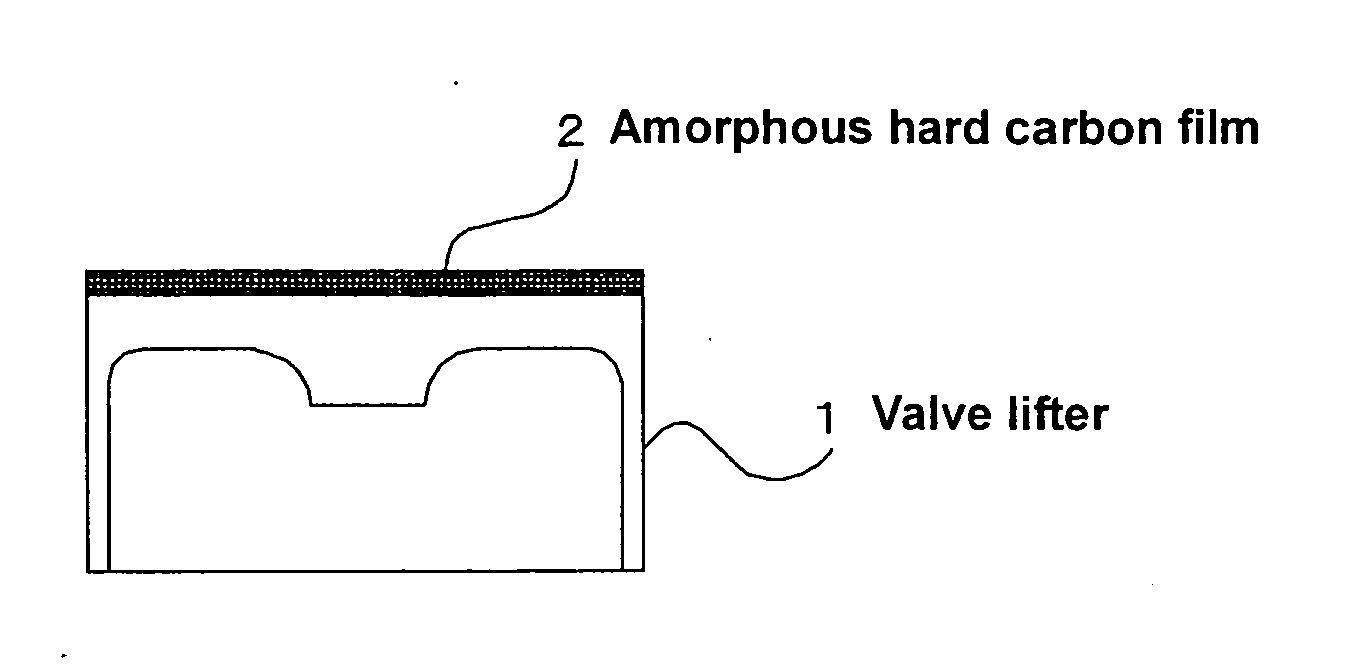
[0025] An exemplary embodiment of a valve lifter according to the present invention is described below.

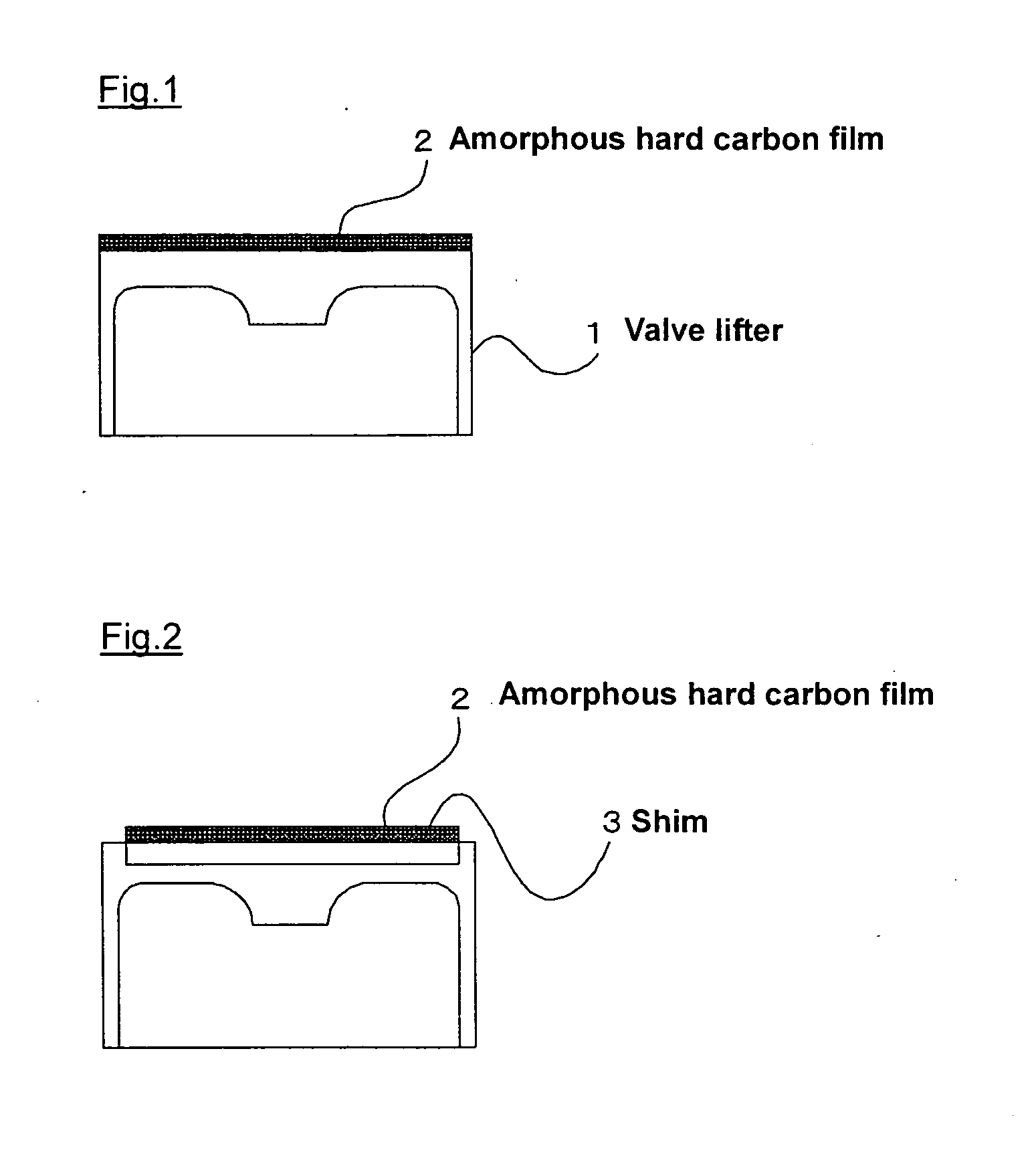
[0026]FIG. 1 and FIG. 2 show examples of cross sectional views of a valve lifter according to the present invention. An amorphous hard carbon film 2 is formed on the top surface of a valve lifter 1 that slides against a cam. For the valve lifter described above, a steel slab, for example, SCM415, is used as a base material of the valve lifter. After the base material is formed by forging, carburizing and quenching is performed, and superfinishing or the like of the top surface is performed in a subsequent process.

[0027]FIG. 2 is an example of a cross sectional view of a valve lifer under a specification that uses a shim 3. In this example, the shim 3 is coated with an amorphous hard carbon film 2, as described herein.

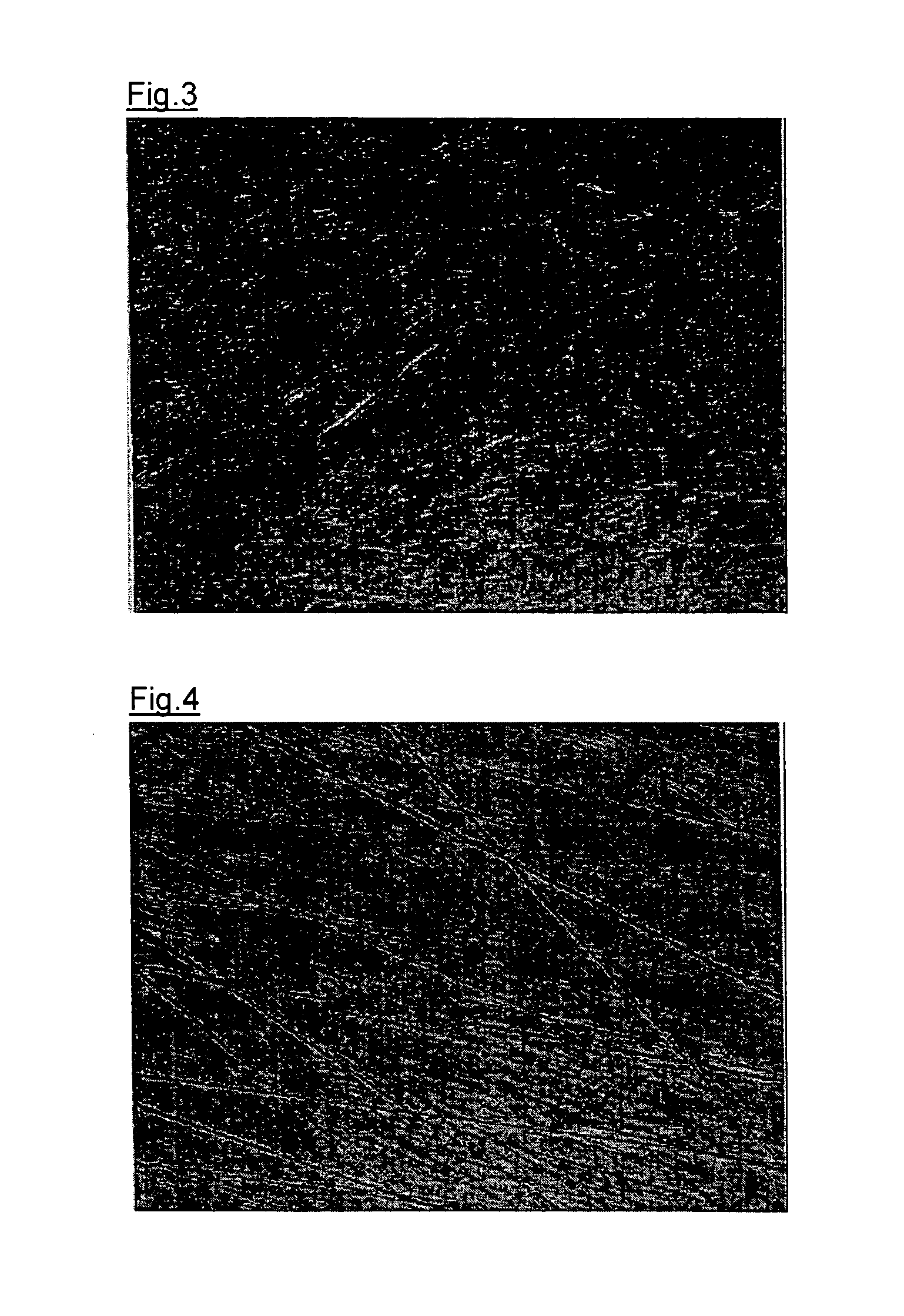
[0028]FIG. 4 is an image of the surface of the top surface portion, on which superfinishing was performed by using a general grindstone, observed with an optical mi...


PUM

PropertyMeasurementUnit
Lengthaaaaaaaaaa
Lengthaaaaaaaaaa
Thicknessaaaaaaaaaa

Abstract

A valve lifter, in which an amorphous hard carbon film is coated at least on the surface that slides against a cam, is characterized in that the surface of a base material (substrate) has an arithmetic mean roughness of Ra 0.01 to 0.03 micrometers, and the maximum length of the scratch on the base surface is made to be equal to or shorter than 250 micrometers.

Description

[0001] This application claims priority to Japanese Patent Application 2005-026719, which was filed Feb. 2, 2005, and is incorporated herein by reference. TECHNICAL FIELD [0002] This invention relates to a valve lifter coated with a hard film and used for a valve train assembly for internal combustion engines. BACKGROUND [0003] In improving fuel efficiency and increasing outputs of an internal combustion engine, to reduce friction at sliding portions in its valve train assembly is an effective measure. Therefore, for the purpose of reducing friction at the sliding portion between a valve lifter and a cam, the sliding surface has been coated with a hard film, such as titanium nitride films (e.g., TiN), chromium nitride films (e.g., Cr2N, CrN), or diamond-like carbon (DLC) films. [0004] To reduce friction, it is necessary that the surface roughness of a shim that is located on the top surface of a valve lifter and slides against a cam, should be as small as the thickness of oil film b...

Claims


Application Information

Patent Timeline
IPC IPC(8): F01L1/16
CPCC23C14/028C23C14/0605F01L1/143Y10T74/2107F01L2101/00F01L2103/00F01L2820/01F01L1/16F01L2301/00F01L2303/00
Inventor MATSUI, TAKASHIMORONUKI, MASAKITSUJI, KATSUHIROMABUCHI, YUTAKAHAMADA, TAKAHIROIZUMI, HIROYUKIKOIKE, TOMOYUKI
Owner RIKEN CO LTD
Why Eureka
Try Eureka