Glazing laminates

a technology of laminates and laminates, applied in the field of glazing laminates, can solve the problems of unsuitable dyes that are barely compatible with the polymer matrices, uneven colour and torn panels, and blotchy panels, so as to reduce heat build-up and minimize heat transmission to the interior

Inactive Publication Date: 2006-09-21
TROPIGLAS
View PDF12 Cites 3 Cited by
  • Summary
  • Abstract
  • Description
  • Claims
  • Application Information

AI Technical Summary

Benefits of technology

[0012] The absorbed IR radiation will be for the most part dispersed in the laminate as heat. In order to minimize the heat transmitted to the interior of the building, the heat is preferably dispersed from the laminate to reduce heat build-up and the black body effect to the interior of a glazed structure.

Problems solved by technology

A practical difficulty experienced with such constructs is that suitable dyes tend to be barely compatible with the polymer matrices in which they are dispersed, and may be reactive with the IR dyes.
The problems range from lack of homogeneity in monolayer films, films changed colour and destroyed the IR properties, and when laminated in two layers to keep the dyes separate, the panels were blotchy, patchy, uneven in colour and torn.

Method used


Image

  • Glazing laminates
  • Glazing laminates
  • Glazing laminates

Examples


example 1

[0050] Methanol was tested for the dissolution of the dyes and of the PVB. BN18 polymer (Wacker-Chemie, PIOLOFORM) was used.

[0051] Initally 2 mg dye / 1 g of PVB mixture was produced and dissolved in ethanol forming a ˜40% solution with respect to the resin. This solution was diluted by methanol to have an overall concentration of 20% of resin. The glass plates were cast in consecutive steps by this solution. During the drying process the layer turned to be turbulent then it cleared. The next consecutive layer was cast in this stage. A dye density of 0.010-0.026 g / m2 covered the individual slides. Additional layers of PVB were cast to have an expected layer thickness of 0.05 mm after the heat treatment. Following by an overnight drying the slides were heat treated at 135° C. for 5-10 min. Two slides were pressed together to have a homogeneous and transparent layer.

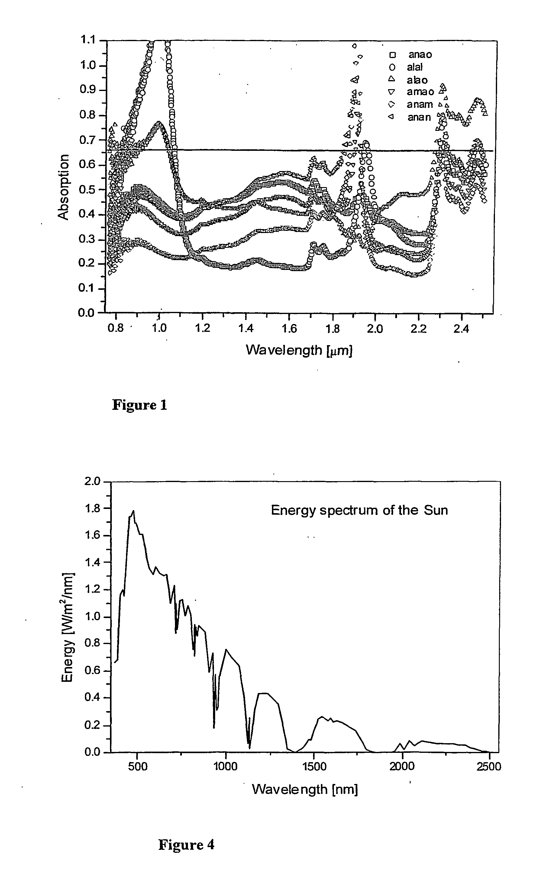
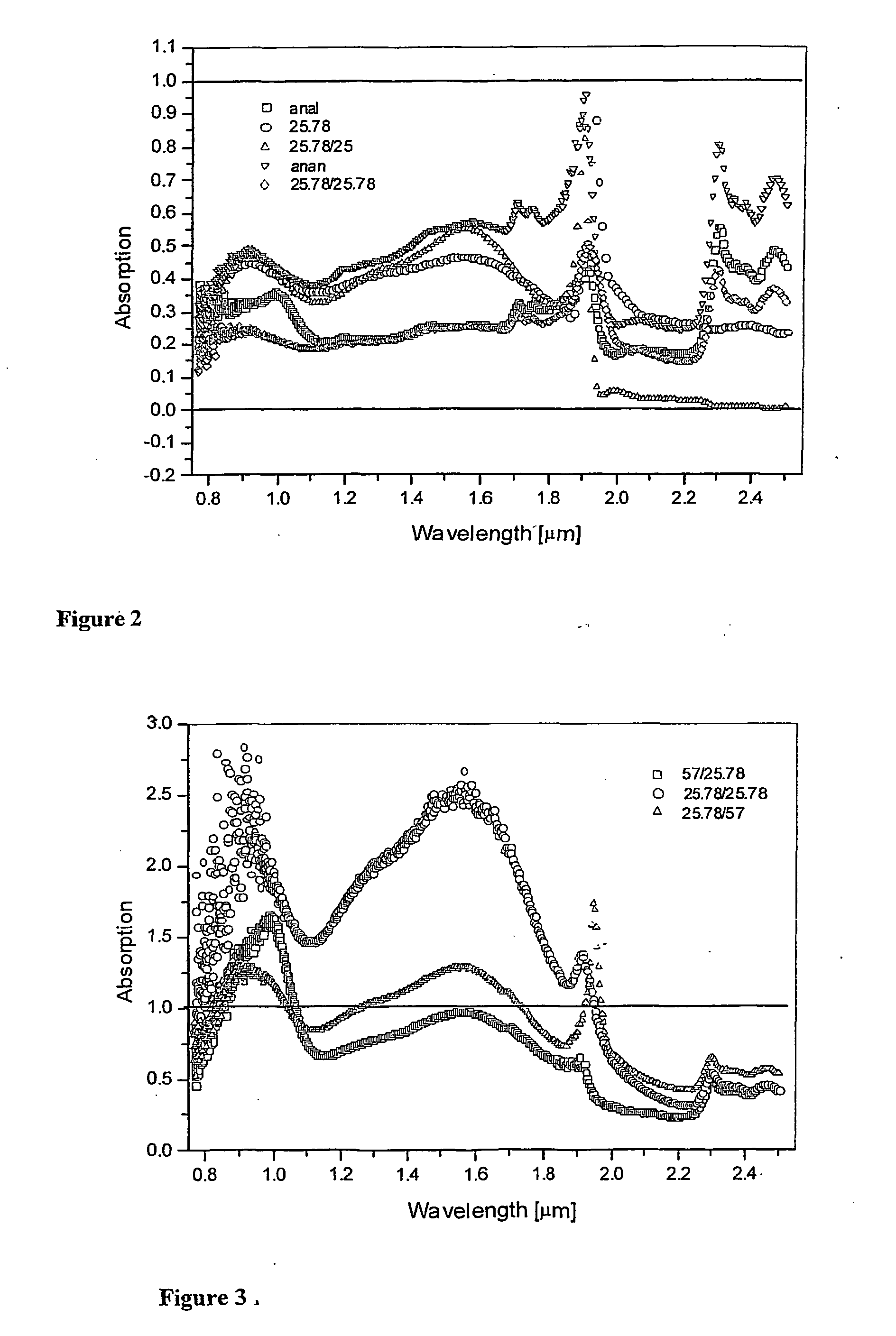
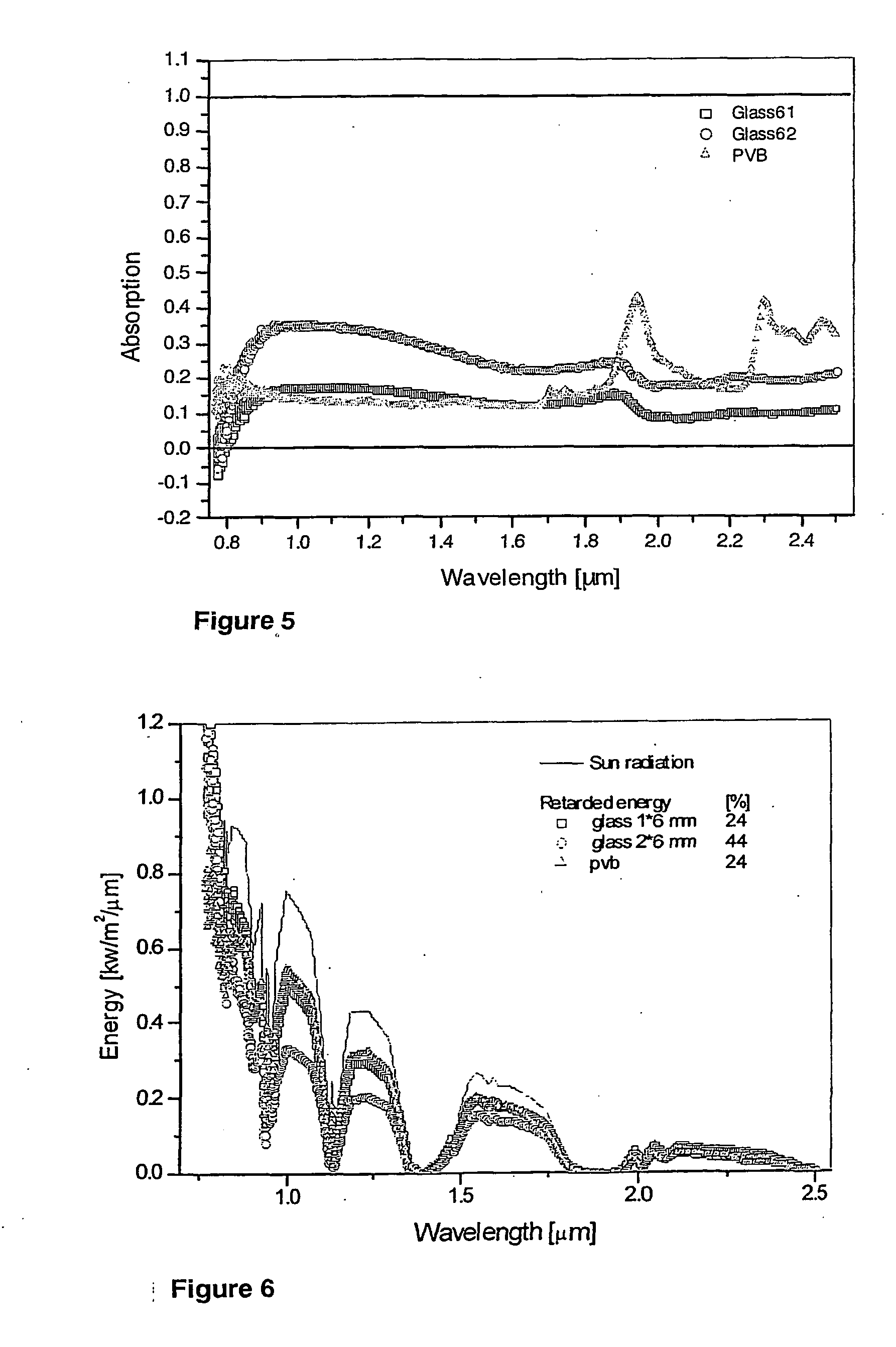
[0052] Four dyes were tested. Epolite 125-(AN), Epolite 178 (AM), Epoline III-57 (AL) and Spectra IR 920 (AO). The combi...

example 2

[0062] Two new dyes were obtained from Epolin Inc. for the purpose of producing blue and grey laminates. The dyes were Sole Blue 33 and Violet B. Epolin give the ratio of colour dye with respect to IR dye of 0.1-0.15 w / w.

[0063] Types of PVB (BN18) and glass used were as previously reported. Methods for preparation were used as previously developed.

[0064] Results

[0065] Sole Blue 33 dissolved well in methanol (5 mg / 10 ml) but Violet B was soluble only up to 1 mg / 10 ml.

[0066] Initial experiments on a small scale were carried out to match the colour to blue or gray from that of the IR dye (i.e. green-yellow). Levels of the new dye of 0.1, 0.3 and 1 w / w dye per IR dye were tested. 4 mg / g IR dye with respect to PVB was used dissolved in 10 ml MeOH / g of PVB.

[0067] Sole Blue 33 dissolved properly at each concentration. However, it did not produce a good colour match—it formed various green colours. Violet B did not dissolve perfectly at the highest concentration—it also produced only a...


PUM

PropertyMeasurementUnit
wavelengthsaaaaaaaaaa

Abstract

There is provided a glazing laminate comprising a polyvinyl butyral core layer having polyvinyl butyral/IR dye layers on each side. The dye containing layers are solvent cast from methanol onto the core layer. The dyes in each layer are different comprising BN 18 type PVB containing either 2 mg Epoline III-125 or 2 mg of Epolite III-57 dyes per grams of resin and dissolved in 10 ml of analytical grade of methanol for casting. The polymer is sandwiched between two glass layers under pressure and heat treatment at 135-140° C. An overall concentration of the dyes of ˜0.1 g/m2 results in an energy absorption over 65%. The heating effect of absorption is reduced by conduction through the polymer to the laminate edges, internal reflection, spherical reradiation and the relative insulative effect of the glass layers.

Description

BACKGROUND OF THE INVENTION [0001] This invention relates to glazing laminates. [0002] This invention has particular but not exclusive application to glazing laminates for glazing in construction, and for illustrative purposes reference will be made to such application. However, it is to be understood that this invention could be used in other applications, such as automotive glass and the like. [0003] A significant contributor to the cost of running commercial buildings or maintenance of comfort in residences is the energy required to provide control of the internal climate of the building. In buildings in hot climates having windows that are exposed to a relatively high flux of solar radiation, or buildings with large areas exposed to solar radiation, a major cost is air cooling by airconditioning. [0004] The conventional means of controlling heat passage into a building is to reduce the flux of solar radiation through the glazing by tinting to reduce a broad spectrum of radiation...

Claims


Application Information

Patent Timeline
Patent Type & Authority Applications(United States)
IPC IPC(8): B32B23/02B32B7/02E06B9/24B32B17/10B32B27/20
CPCY10T428/24777B32B17/10339
Inventor CSER, FERENCCALLARD, LLOYDM
Owner TROPIGLAS
Why Eureka
Try Eureka