Backlight device and liquid crystal display
- Summary
- Abstract
- Description
- Claims
- Application Information
AI Technical Summary
Benefits of technology
Problems solved by technology
Method used
Image

Examples
first embodiment
Light Source; Cold Cathode Ray Tube
[0058] Initially, a liquid crystal display apparatus, shown as a first embodiment of the present invention, will be explained.
(Structure of the Liquid Crystal Display Apparatus)
[0059] A liquid crystal display apparatus, shown as a first embodiment, uses a cold cathode ray tube, which is a line light source, as a light source of the subjacent backlight device.
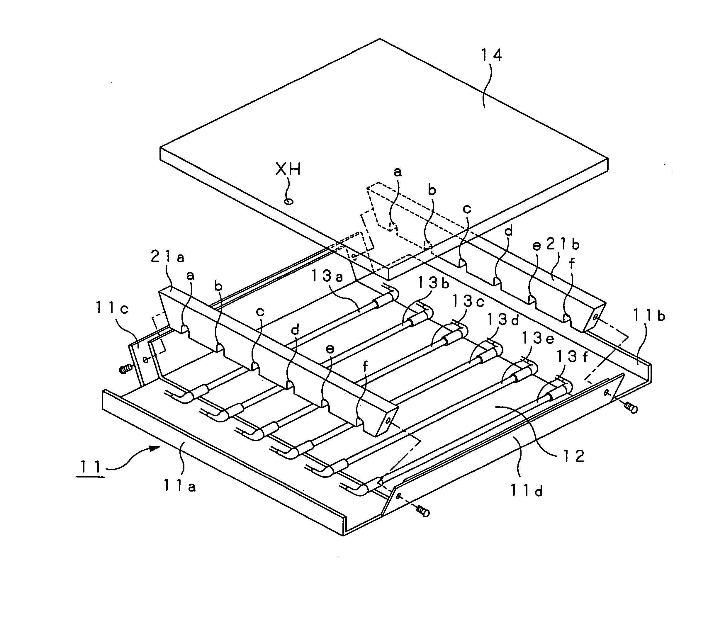
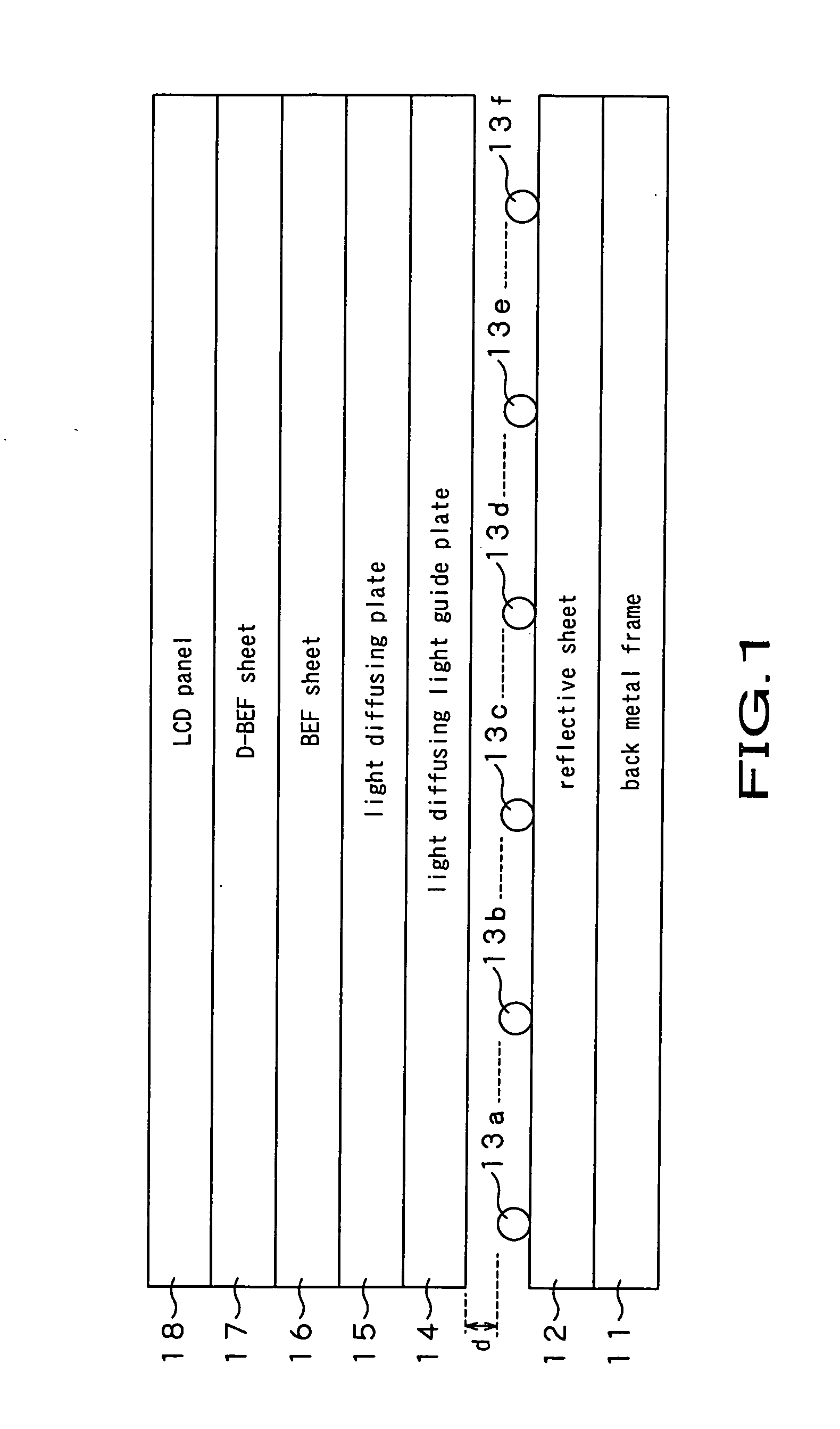
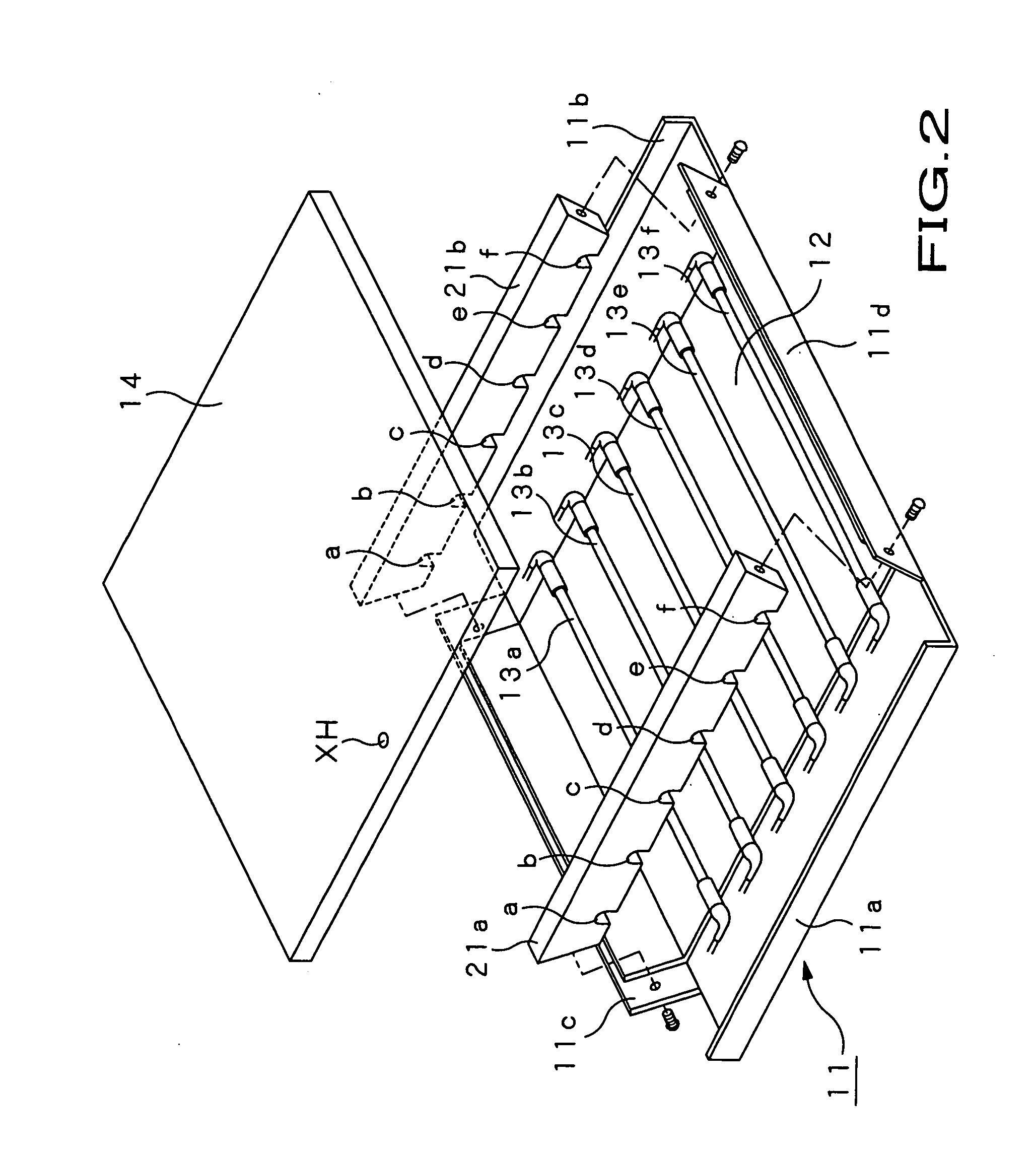
[0060] This backlight device includes plural cold cathode ray tubes (for example, fluorescent tubes 13a to 13f of FIG. 1) and a light diffusing plate, including a transmittance for all light rays of 62 to 71%, in the direction of light projection of the plural cold cathode ray tubes (e.g. fluorescent tubes 13a to 13f of FIG. 1) and a cloud value of 90 to 99%, and having a light dimming dot pattern printed thereon, such as a light diffusing plate 15 of FIG. 1. The backlight device is characterized by the fact that the dots of the light dimming dot pattern are disposed at points resulting fr...
second embodiment
Light Source Being a Light Emitting Diode
[0148] A liquid crystal display apparatus, shown as a second embodiment of the present invention, will now be explained.
(Structure of the Liquid Crystal Display Apparatus)
[0149] A liquid crystal display apparatus 100, shown as a second embodiment in FIG. 16, uses a light emitting diode, which is a point light source, as a light source for a subjacent backlight device 140.
[0150] The light transmitting liquid crystal display apparatus 100 is made up by a light transmitting liquid crystal display panel 110, and the backlight device 140, arranged on the back surface of the liquid crystal display panel 110. This liquid crystal display panel 110 also includes a receiver, such as analog or digital tuner, receiving ground waves or satellite waves, a picture signal processor and an audio signal processor for processing picture signals and audio signals, captured by the receiver, or an audio signal outputting unit, such as a loudspeaker, for outpu...
example 1
[0206] In an Example 1, a backlight device 140, illuminating a 46 inch liquid crystal display panel 110, as shown in FIG. 26, is used.
[0207] In this example, a backlight unit 121n, having a plural number of light emitting diodes 121, with a set of a green light emitting diode 121G, a red light emitting diode 121R, a green light emitting diode 121G and a blue light emitting diode 121B, as a repetitive unit, was arrayed so that the longitudinal direction of the array will become the horizontal direction of the backlight device 140, as shown in FIG. 17. A number of the backlight unit 121n were arrayed side-by-side with a pitch between neighboring backlight unit 121n of 80 mm.
[0208] The light diffusing light guide plate 125, provided to the backlight device 140, is formed of polyolefin with transmittance for all light rays of 90% and a cloud value of 70%.
[0209] Two of the light diffusing light guide plates 125 are provided and no printing is made on one of the plates while a light di...
PUM
 Abstract
Description
Claims
Application Information
 - Generate Ideas
- Intellectual Property
- Life Sciences
- Materials
- Tech Scout
- Unparalleled Data Quality
- Higher Quality Content
- 60% Fewer Hallucinations
Browse by: Latest US Patents, China's latest patents, Technical Efficacy Thesaurus, Application Domain, Technology Topic, Popular Technical Reports.
© 2025 PatSnap. All rights reserved.Legal|Privacy policy|Modern Slavery Act Transparency Statement|Sitemap|About US| Contact US: help@patsnap.com