Adjustable and fixed assembled bone-tendon-bone graft
- Summary
- Abstract
- Description
- Claims
- Application Information
AI Technical Summary
Benefits of technology
Problems solved by technology
Method used
Image
Examples
example 1
Intermediate Bone Blocks of the Invention Having an Omega-Shaped Cross-Section
A. Plank with Two Substantially Parallel Channels Having an Omega-Shaped Cross-Section:
[0162] Cortical bone from a long bone shaft was cut into planks using a band saw. Bone planks were then cut into rectangular bone blanks of rough dimensions 10 mm×5 mm×25 mm using a mill (Haas Automation, Oxnard, Calif.; model # TM-1, serial # 34798). Each blank is then squared up and surface cut (planed) to final dimensions. One of the squared up bone blanks was laid out and templated for cutting two channels running the length of the bone blank and substantially parallel to the sidewalls of the bone blank. The rough outlines of the omega-shaped channels were cut with a 1.0 mm diameter end mill cutter. A 2.4 mm diameter ball end mill ( Dremel, Racine Wis.; Dremel # 107) was used to complete the omega-shaped channels as shown in FIG. 11, for the final dimensions of 1.8 mm deep.
B. Plank with a Single “U”-Shaped Layou...
example 2
Bone Block Assembly Comprising an Intermediate Bone Block and a Second Bone Block
A. Bone Block of FIGS. 6A-6D with Saw Tooth Pattern of Ridges
[0167] Cortical bone planks were cut from a long bone shaft using a band saw. Bone planks were then cut into rectangular bone blanks of rough dimensions 10 mm×5 mm×25 mm using a mill (Haas Automation, Oxnard, Calif.; model # TM-1, serial # 34798). The mill was used to cut the serrated pattern of FIGS. 6A-6D on the upper block from a bone blank, at 0.76 mm deep, with a pitch of 0.8 teeth per mm, and at tooth angle of 30 degrees.
B. Intermediate Bone Block of FIGS. 11A-11D
[0168] The bone block of Example 2A was clamped to a surface with its ridge side up and the rough outline of two substantially parallel channels with an omega-shaped cross section were cut into the block with a 1.0 mm end mill cutter. A 2.4 mm diameter ball end mill (Dremel, Racine Wis.; Dremel # 107) was used to complete the two omega-shaped channels to produce the interme...
example 3
A Bone Tendon Assembly for Testing Grip of Bone Patterns
A. Bone Block with a Smooth Tendon Engaging Surface
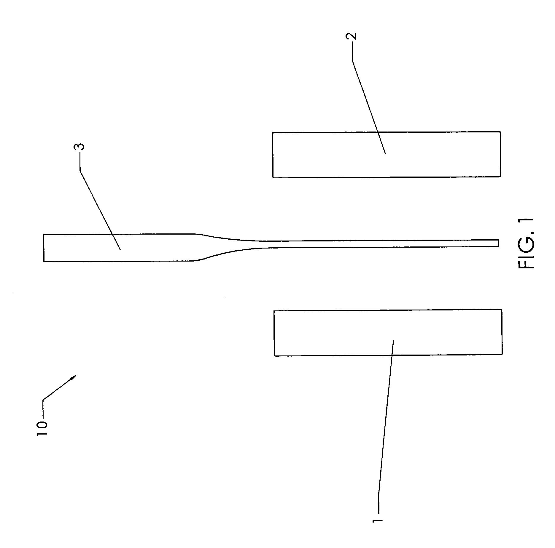
[0169] Cortical bone from a long bone shaft were cut into planks using a band saw. Bone planks were then cut into rectangular bone blanks of rough dimensions 10 mm×5 mm×25 mm using a mill (Haas Automation, Oxnard, Calif.; model # TM-1, serial # 34798). Each blank is then squared up and surface cut (planed) to final dimensions. A pair of these bone blocks were used to make the bone block-tendon assembly of FIG. 1.
B. Bone Block with a Saw Tooth Pattern on the Tendon Engaging Surface of 0.8 Teeth Per mm, 0.76 mm Deep, at a 30 Degree Angle to the Direction of Pull of the Tendon
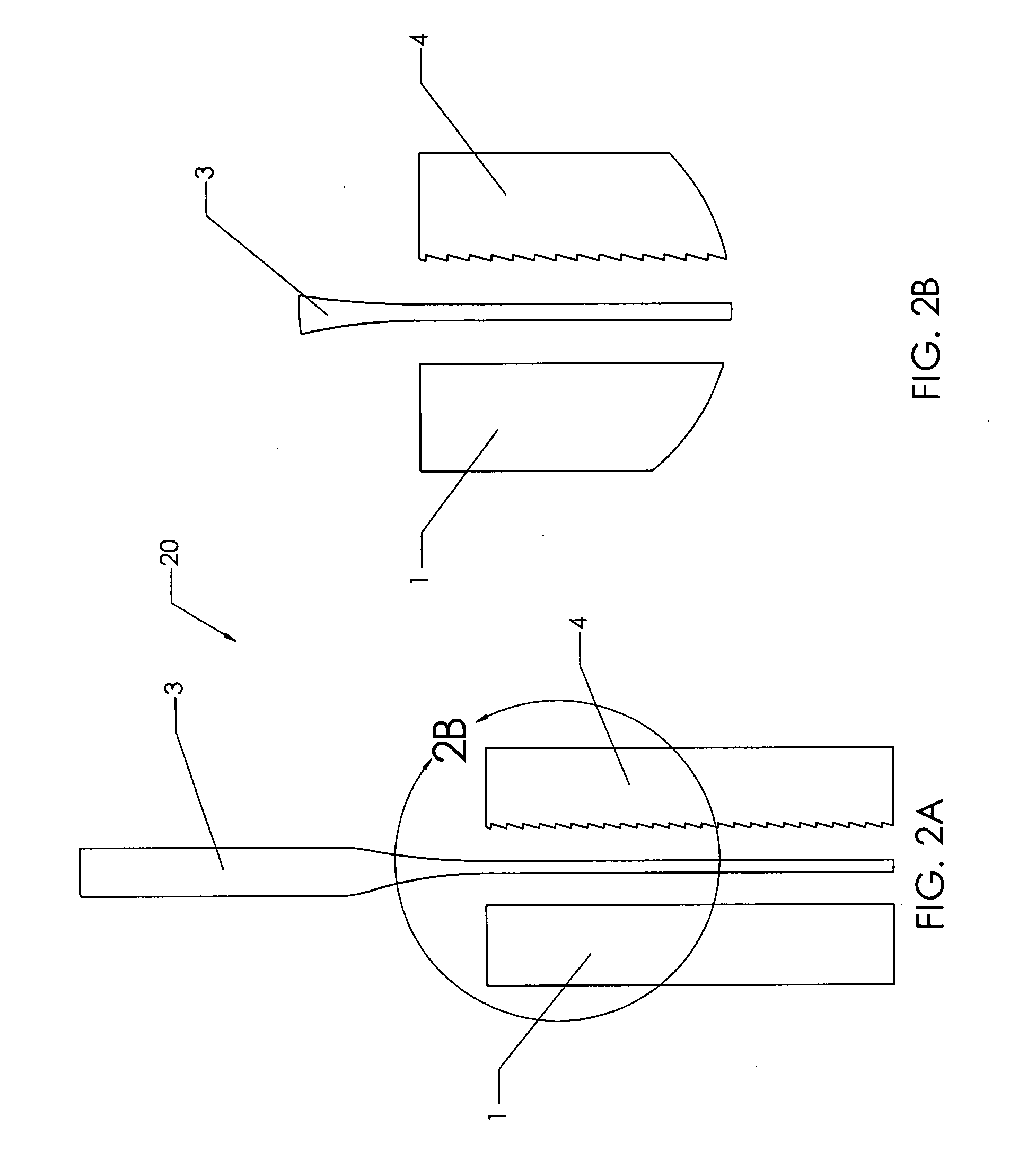
[0170] Cortical bone planks were cut from a long bone shaft using a band saw. Bone planks were then cut into rectangular bone blanks of rough dimensions 10 mm×5 mm×25 mm using a mill (Haas Automation, Oxnard, Calif.; model # TM-1, serial # 34798). The mill was used to cut the serrated pattern of FIGS. 6...
PUM
 Abstract
Description
Claims
Application Information
 - R&D
- Intellectual Property
- Life Sciences
- Materials
- Tech Scout
- Unparalleled Data Quality
- Higher Quality Content
- 60% Fewer Hallucinations
Browse by: Latest US Patents, China's latest patents, Technical Efficacy Thesaurus, Application Domain, Technology Topic, Popular Technical Reports.
© 2025 PatSnap. All rights reserved.Legal|Privacy policy|Modern Slavery Act Transparency Statement|Sitemap|About US| Contact US: help@patsnap.com


