
Dielectric porcelain composition, electronic device and methods for producing these

Active Publication Date: 2006-10-19
TDK CORPARATION
View PDF7 Cites 10 Cited by
  • Summary
  • Abstract
  • Description
  • Claims
  • Application Information

AI Technical Summary

Benefits of technology

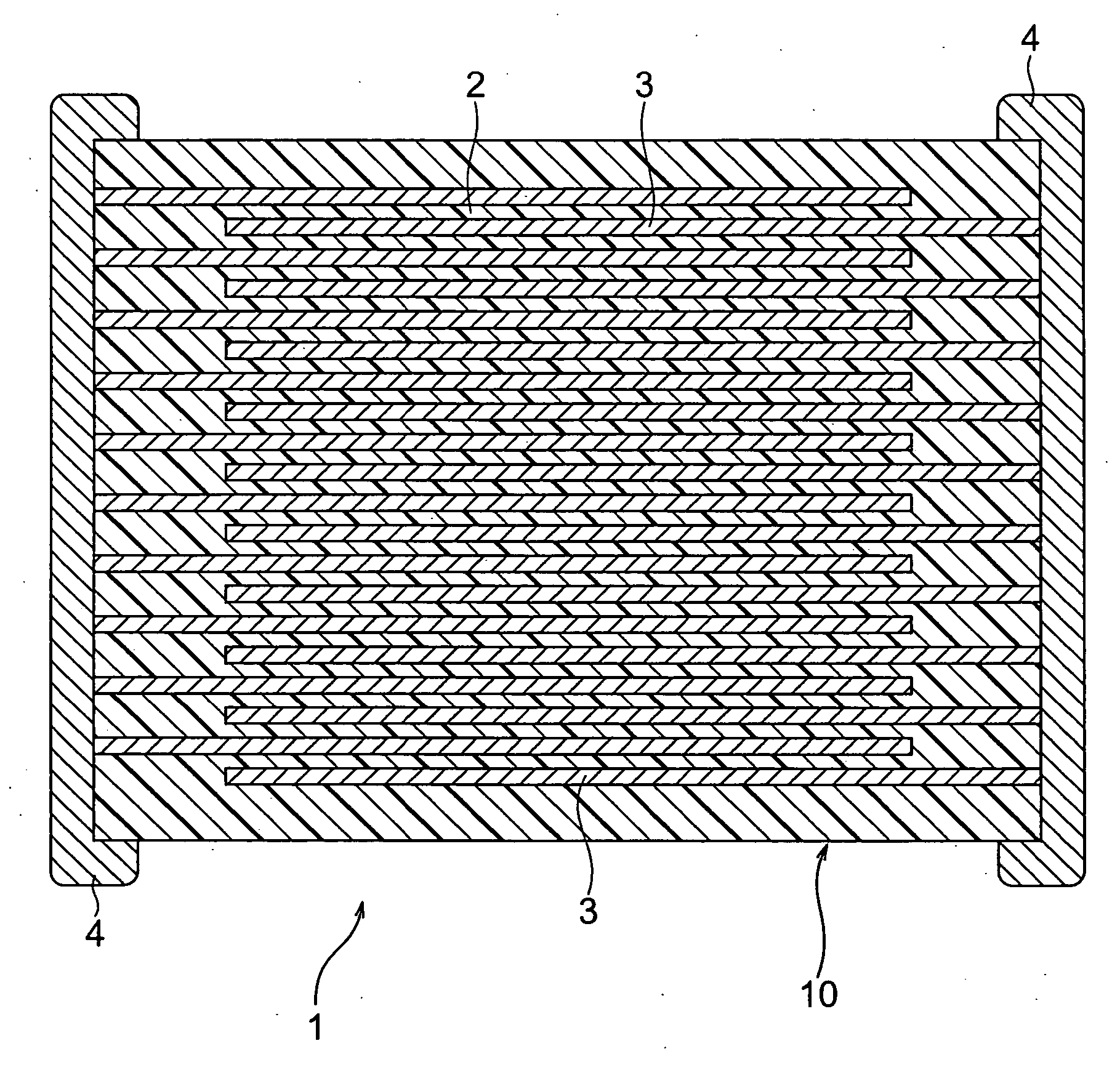
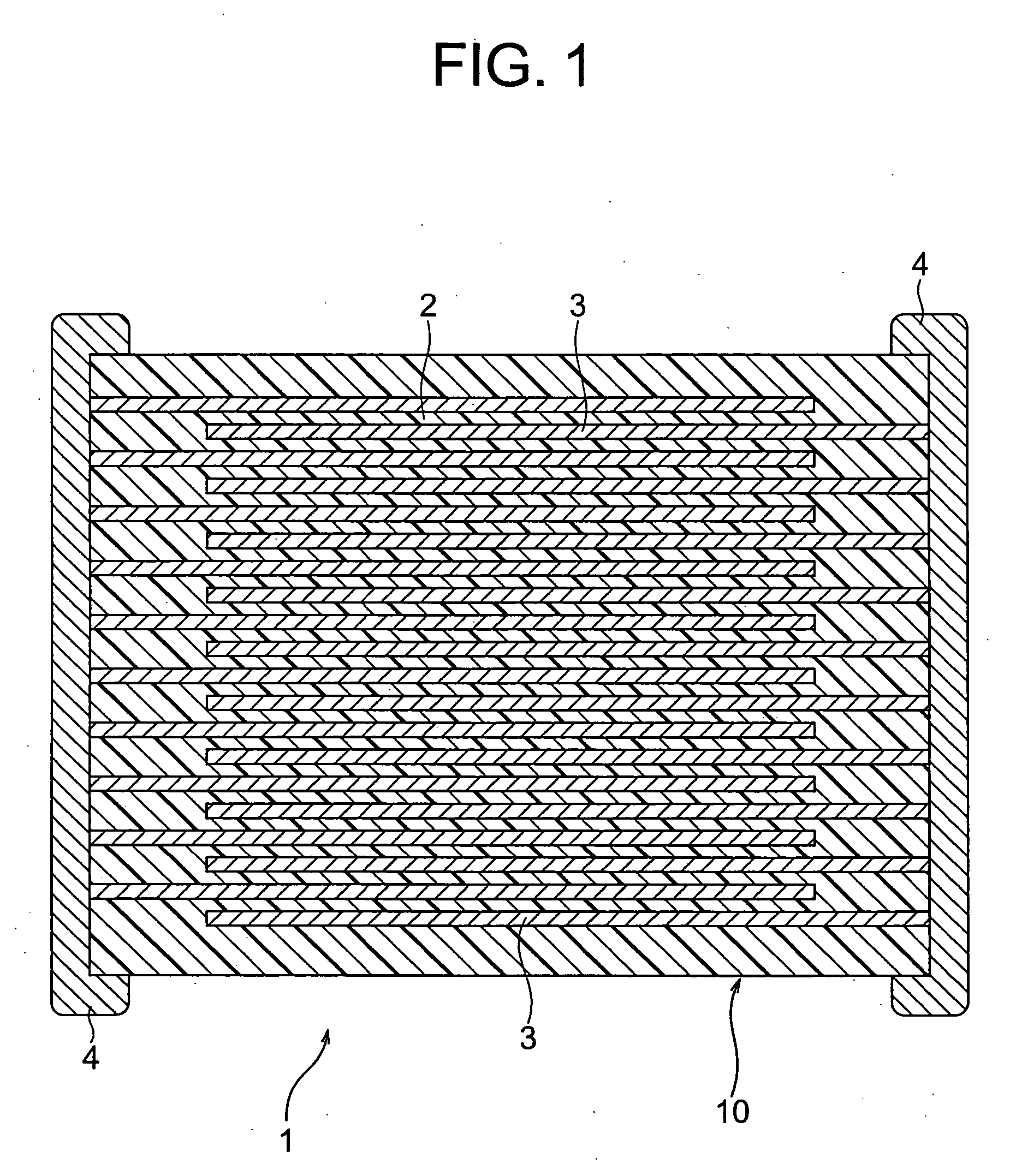
[0012] The present invention was made in consideration of the above circumstances and has as an object thereof to provide highly reliable nonreducing dielectric ceramic composition preferably used as a dielectric layer of a multilayer ceramic capacitor, etc. using Ni or other base metal as the internal electrode, and able to be sintered at 1300° C. or lower, wherein a temperature coefficient of the capacitance is small and able to be freely controlled in a range of −15 to +150 ppm / ° C., the insulation resistance at 25° C. is 1×10¹³Ω or higher, the specific permittivity and dielectric loss tangent (tan δ) have a little frequency dependency, accelerated lifetime of the insulation resistance is long and, moreover, a defect rate of the insulation resistance is low even when the insulation layer is made thin.
[0023] The dielectric ceramic composition according to the present invention basically has approximately the same composition as that in the patent article 1, so that it is possible to provide a highly reliable nonreducing dielectric ceramic composition able to be sintered at 1300° C. or lower, wherein a temperature coefficient of the capacitance is small and able to be freely controlled in a range of −15 to +150 ppm / ° C., the insulation resistance at 25° C. is 1×10¹³Ω or higher, the specific permittivity and dielectric loss tangent (tan δ) have a little frequency dependency, and accelerated lifetime of the insulation resistance is long even when the insulation layer is made thin.
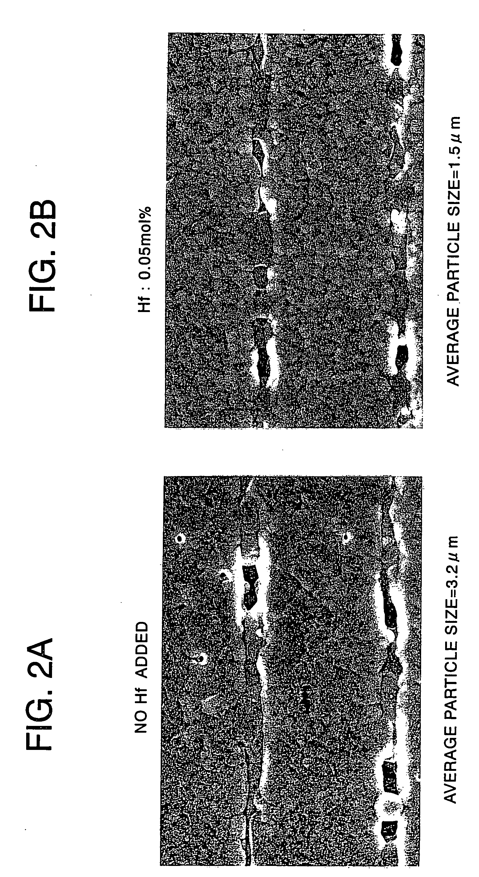
[0025] As a result, according to the present invention, unevenness of insulation resistance caused by unevenness of the boundary face due to cracks, delamination or an uneven crystal can be suppressed.
[0049] In the method of the present invention, solid solubility of the glass component and subcomponents to the main component is uniformly accelerated, so that reactivity becomes gentle in main firing and abrupt grain growth can be suppressed. As a result, crystal particle diameters become uniform and fine and able to be sufficiently sintered at a temperature of 1300° C. or lower, so that it becomes possible to realize a thinner layer. Also, in the method of the present invention, a stress from the internal electrode is lightened when thermally contracted at the time of the main firing, so that crack defectives are reduced.

Problems solved by technology

However, experiments by the present inventors proved that the dielectric ceramic composition described in the above patent article 1 has uneven insulation resistance and is hard to reduce the insulation resistance defect rate.

Method used


Image

  • Dielectric porcelain composition, electronic device and methods for producing these
  • Dielectric porcelain composition, electronic device and methods for producing these
  • Dielectric porcelain composition, electronic device and methods for producing these

Examples


example 1

[0132] First, as starting materials for producing a dielectric material, main component materials (SrCO3, CaCO3, TiO2, ZrO2 and HfO2) and subcomponent materials (including a glass component) each having an average particle diameter of 0.1 to 1.5 μm were prepared. As the subcomponent materials, carbonate (MnO3 and BaCO3) or oxides (Al2O3, SiO2 and Y2O3, etc.) were used.

[0133] After weighing the materials, so that a composition after firing would be the composition shown in Table 1 below, water as a medium was added to the materials and mixed by a ball mill for 16 to 40 hours to perform high dispersion mixing. After that, the mixture was dried, then, calcinated under a condition of 1100 to 1300° C. for 2 to 4 hours. Thus obtained calcinated substance was subjected to wet grinding by a ball mill and dried.

[0134] With 100 parts by weight of the thus obtained dried dielectric material, 4.8 parts by weight of an acrylic resin, 40 parts by weight of methylene chloride, 20 parts by weight...

example 2

[0164] Other than weighing the materials, so that a composition after firing would be the composition shown in Table 3 below, capacitor samples were produced in the same way as in the example 1 and the same evaluation was made as that in the example 1. The results are shown in Table 4.

TABLE 3Subcomponent 1Subcomponent 2mol % withmol % with respectMain Componentrespect toGlass Componentto 100 mol ofMole Ratios100 mol[(BavCa1−v)O]wSiO2AddingMain ComponentSamplein [(CaxSr1−x)O]m[(TiyZr1−y−zHfz)O2]of Main ComponentMole RatiosQuantityAddingNo.x1 − xy1 − y − zzmMnOAl2O3v1 − vwmol %AdditiveQuantity260.70.30.050.90.05110.50113——270.70.30.050.90.05110.50.10.913——280.70.30.050.90.05110.51013——※290.70.30.050.90.05110.50.50.50.43——300.70.30.050.90.05110.50.50.50.53——310.70.30.050.90.05110.50.50.543——※320.70.30.050.90.05110.50.50.54.13——※330.70.30.050.90.05110.50.50.510.4——340.70.30.050.90.05110.50.50.510.5——350.70.30.050.90.05110.50.50.5115——※360.70.30.050.90.05110.50.50.5116——

[0165]

TABLE 4El...

example 3

[0170] Other than weighing the materials, so that a composition after firing would be the composition shown in Table 5 below, capacitor samples were produced in the same way as in the example 1, and the same evaluation was made as that in the example 1. The results are shown in Table 6.

TABLE 5Subcomponent 1Subcomponent 2mol % withmol % with respectMain Componentrespect toGlass Componentto 100 mol ofMole Ratios100 mol[(BavCa1−v)O]wSiO2AddingMain ComponentSamplein [(CaxSr1−x)O]m[(TiyZr1−y−zHfz)O2]of Main ComponentMole RatiosQuantityAddingNo.x1 − xy1 − y − zzmMnOAl2O3v1 − vwmol %AdditiveQuantity※370.70.30.050.90.05110.50.50.413Mg0.01380.70.30.050.90.05110.50.50.413Mg0.02390.70.30.050.90.05110.50.50.413Mg0.5400.70.30.050.90.05110.50.50.413Mg1.5※410.70.30.050.90.05110.50.50.413Mg2420.70.30.050.90.05110.50.50.413Sc0.5430.70.30.050.90.05110.50.50.413Y0.5440.70.30.050.90.05110.50.50.413La0.5450.70.30.050.90.05110.50.50.413Ce0.5460.70.30.050.90.05110.50.50.413Pr0.5470.70.30.050.90.05110.50...


PUM

PropertyMeasurementUnit
Temperatureaaaaaaaaaa
Lengthaaaaaaaaaa
Particle diameteraaaaaaaaaa

Abstract

A dielectric ceramic composition, comprising a main component including at least a dielectric oxide having a composition expressed by [(CaxSr1-x)O]m[(TiyZr1-y-zHfz)O2], a first subcomponent including a Mn oxide and / or an Al oxide and a glass component, wherein “m”, “x”, “y” and “z” indicating composition mole ratios in the formula included in the main component are in relationships of 0.90≦m≦1.04, preferably 1.005≦m≦1.025, 0.5≦x<1, preferably 0.6≦x≦0.9, 0.01≦y≦0.10, preferably 0.02≦y≦0.07 and 0<z≦0.20, preferably 0<z≦0.10.

Description

BACKGROUND OF THE INVENTION [0001] 1. Field of the Invention [0002] The present invention relates to a dielectric ceramic composition, an electronic device and production methods of them, and particularly relates to a nonreducing temperature compensating dielectric ceramic composition preferably used for an electronic device, such as a multilayer ceramic capacitor, using a base metal as an internal electrode thereof. [0003] 2. Description of the Related Art [0004] Multilayer ceramic capacitors are widely used as electronic devices, and the number used in one electronic device is also large. A multilayer ceramic capacitor is normally produced by stacking an internal electrode layer paste and a dielectric layer paste by a sheet method or a printing method, etc. and cofiring the result. [0005] A dielectric ceramic material used for a multilayer ceramic capacitor, etc. of the related art has a property of getting reduced and becoming a semiconductor when fired in a reducing atmosphere. ...

Claims


Application Information

Patent Timeline
IPC IPC(8): C04B35/465C04B35/48C04B35/49C04B35/638H01B3/02H01B3/12H01G4/10H01G4/12H01G4/30
CPCB32B18/00Y10T428/24926C04B35/49C04B35/6262C04B35/6263C04B35/6264C04B35/63C04B35/638C04B35/64C04B2235/3206C04B2235/3208C04B2235/3213C04B2235/3217C04B2235/3224C04B2235/3225C04B2235/3227C04B2235/3229C04B2235/3239C04B2235/3251C04B2235/3256C04B2235/3258C04B2235/3262C04B2235/36C04B2235/6582C04B2235/6584C04B2235/663C04B2235/785C04B2235/786C04B2235/79C04B2235/96C04B2237/346C04B2237/348C04B2237/405C04B2237/704H01B3/12H01G4/10H01G4/1245B32B2311/22H01B3/02H01G4/12
Inventor SASAKI, HIROSHITANAKA, HITOSHINIWA, YASUOWATANABE, MATSUMINONAKA, TOMOAKI
Owner TDK CORPARATION
Learn More