Exhaust gas component analyzer

Active Publication Date: 2006-10-26
HORIBA LTD
View PDF11 Cites 36 Cited by
  • Summary
  • Abstract
  • Description
  • Claims
  • Application Information

AI Technical Summary

Benefits of technology

[0033] As a result of this, it is possible to realize the exhaust gas analyzer of a vehicle-mountable type tha

Problems solved by technology

With these analyzers, other components in the exhaust gas cause interference or quenching to the component as an object to be measured due to a system of these analyzers, thereby causing an error in the measurement result.
However, in case that interference is caused due to multiple components for the chemiluminescence nitrogen oxide analyzer, it is necessary to provide multiple detectors to correct interference for each component, resulting in complicated arrangement.
In addition, if the flow rate of the exhaust gas is decreased or the exhaust gas is diluted for the chemiluminescence nitrogen oxide analyzer, the sensitivity or the precision is degraded, and the response of the measurement is also affected.
These problems such that the arrangement becomes complicated or large, or the measurement sensitivity, the measurement accuracy and the response of the measurement are degraded are a bottleneck for developing an exhaust gas analyzer that can be mounted on a vehicle and that can measure the exhaust gas continuously on a real time basis.
In addition, a conventional vehicle-mountable exhaust gas analyzer is provided with a heated piping or dehumidifier to remove moisture

Method used


Image

  • Exhaust gas component analyzer
  • Exhaust gas component analyzer
  • Exhaust gas component analyzer

Examples


Embodiment Construction

[0037] An exhaust gas analyzer 100 in accordance with one embodiment of the present claimed invention will be described in detail with reference to the accompanying drawings.

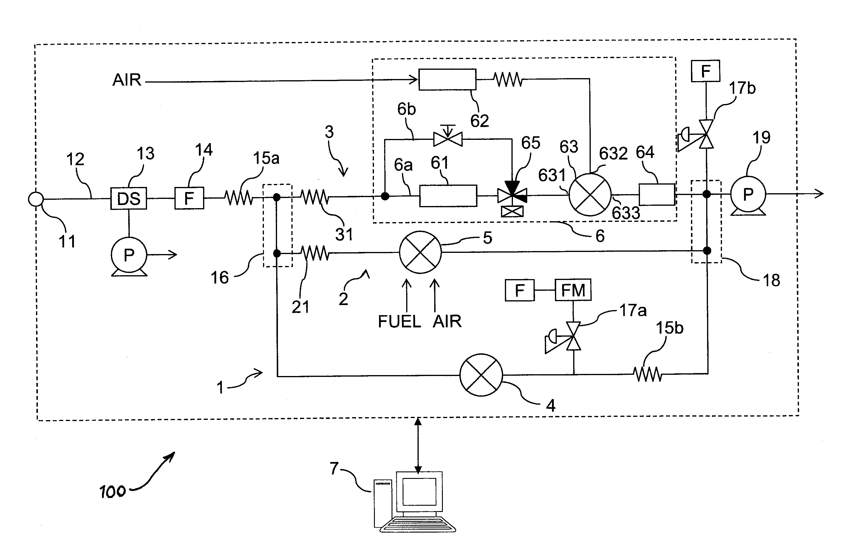
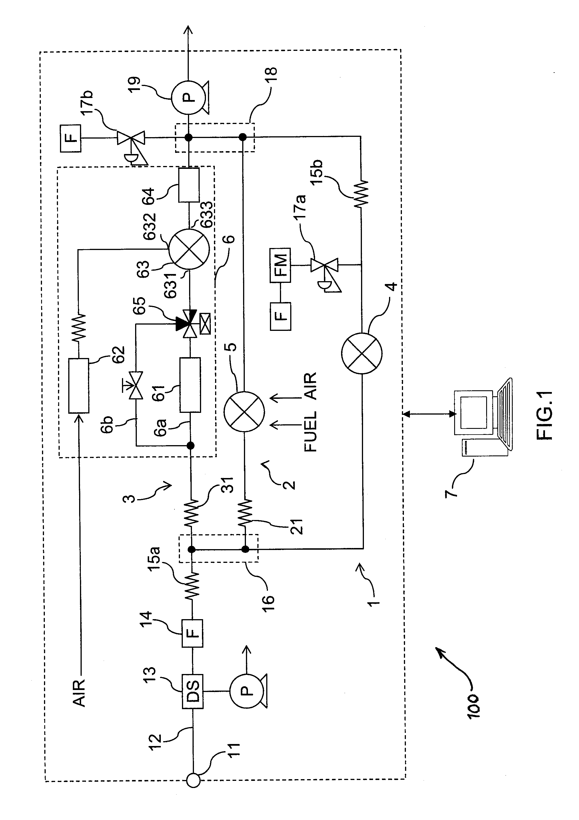
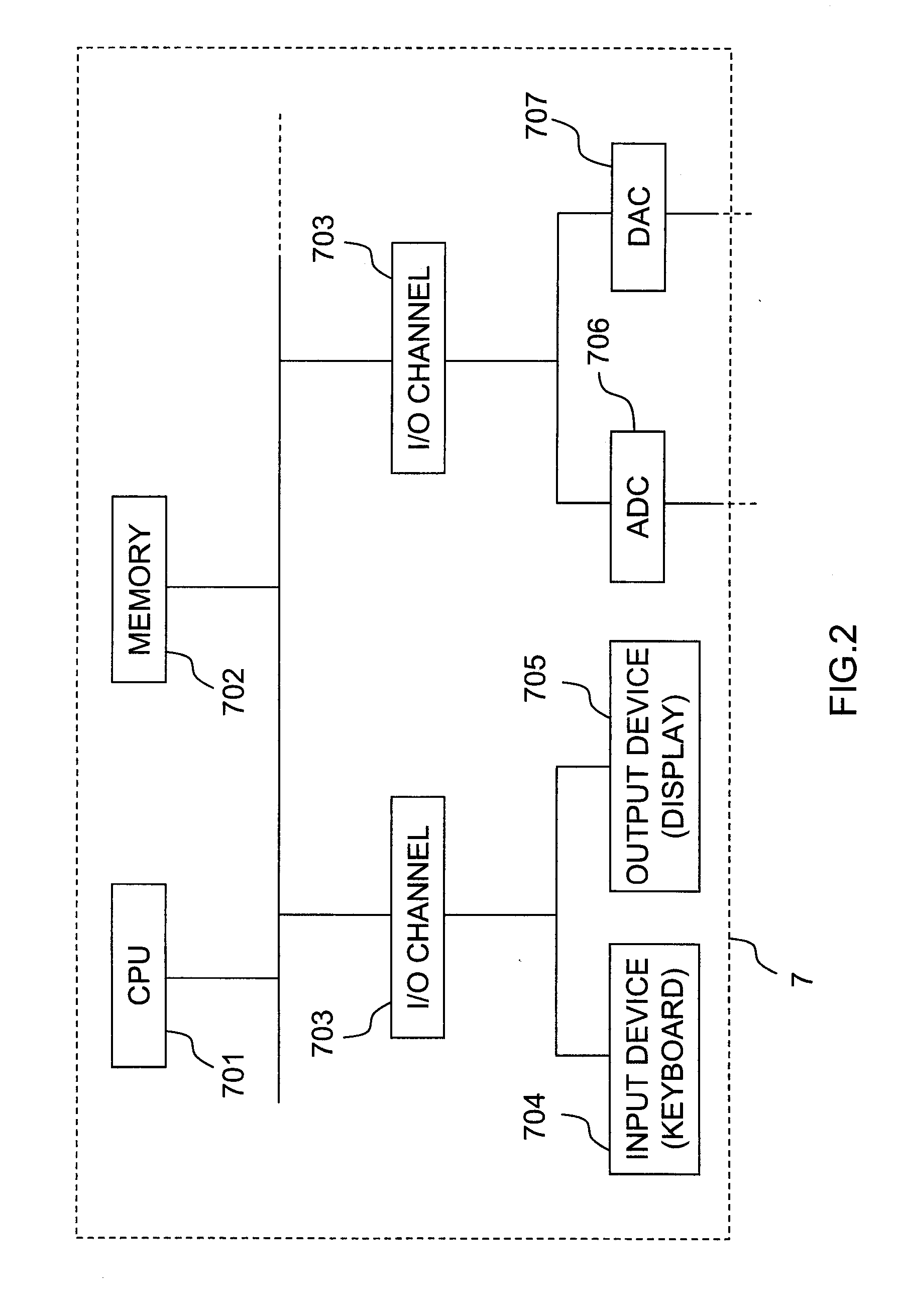
[0038] The exhaust gas measuring system 100 in accordance with this embodiment is to measure concentration of various components in exhaust gas while a vehicle is actually in motion with the exhaust gas measuring system 100 loaded on a trunk of the vehicle and, as shown in FIG. 1, comprises three different analyzers 4, 5, 6, a flow path system for supplying the exhaust gas continuously to the analyzers 4, 5, 6, and an information processing unit 7 that receives actual measurement data from each analyzer 4, 5, 6 and analyzes them, that calculates true measurement values, and that controls a valve arranged in the flow path system.

[0039] Each component will be described.

[0040] First, an infrared gas analyzer 4 to measure each concentration of CO, CO2, H2O, a hydrogen flame ionization analyzer 5 to measure concen...


PUM


Abstract

An exhaust gas analyzer includes a main flow path and at least one sub-flow path. Exhaust gas from an internal combustion engine is introduced to the main flow path; sub-flow paths are parallel to the main flow path. Plural kinds of analyzers are mounted on the main flow path and sub-flow paths to measure concentration of multiple components in the exhaust gas. Actual measurement values of the concentration for the measured components are obtained. A deviance from a true value generated to an actual measurement value due to a mutual influence of the measured components is corrected based on at least one actual measurement value.

Description

BACKGROUND OF THE INVENTION [0001] 1. Field of the Invention [0002] This invention relates to a multiple component gas analyzer that analyzes various components contained in exhaust gas from vehicles. [0003] 2. Background Art [0004] Conventionally, various gas analyzers are used in order to measure components in exhaust gas discharged from a vehicle such as an automobile. For example, as shown in Japan Patent laid open no. 11-230869, an infrared gas analyzer is used in order to measure the concentration of CO or CO2 and a chemiluminescence nitrogen oxide analyzer is used in order to measure the concentration of NOX. In addition, a hydrogen flame ionization analyzer to measure the concentration of THC (total hydro carbon) is also well-known. [0005] With these analyzers, other components in the exhaust gas cause interference or quenching to the component as an object to be measured due to a system of these analyzers, thereby causing an error in the measurement result. As a result, for...

Claims


Application Information

Patent Timeline
IPC IPC(8): G01M15/10
CPCG01N33/0032G01N33/0047G01N33/004G01N33/0037Y02A50/20
Inventor NAKAMURA, HIROSHI
Owner HORIBA LTD
Why Eureka
Try Eureka