Gas separation vessel apparatus

a technology of gas separation vessel and gas product, which is applied in the direction of chemistry apparatus and processes, separation processes, dispersed particle separation, etc., can solve the problems of vessel not meeting the need for a means, affecting the overall consistency of gas product purity, and reducing the efficiency of the vessel, so as to achieve convenient onsite installation and reduce the need for means. , the effect of reducing the size and weigh

Inactive Publication Date: 2006-10-26
AES DEV CO
View PDF15 Cites 58 Cited by
  • Summary
  • Abstract
  • Description
  • Claims
  • Application Information

AI Technical Summary

Benefits of technology

[0025] A third embodiment of the invention responds to need wherein a vertical RFBC vessel assembly apparatus configuration is particularly suited to, but not limited to, smaller volume rated air or gas process streams. In this embodiment, the design of the RFBC vessel assembly apparatus is specific to the invention installed in a vertical-axis plane. The vertical positioning and vessel vertical design dimensions can permit easily manageable onsite installation or removal / replacement of individual RFBC subassemblies that are typically smaller in size and of lesser weight than those applied within large capacity flow process streams. There can be variances to the third embodiment of the invention, as described later.

Problems solved by technology

The described current art vertical vessel configurations share many common limitations that negatively impact the vessel's overall consistent gas product purity, maintenance of operating adsorbent bed uniformity and adsorbent structural form integrity, and economical power consumption.
Previous art vessels have not addressed the need for a means to carry out a rapid and economical adsorbent bed removal and replacement as new improved performance adsorbent materials become available, or when the existing adsorbent bed becomes contaminated from a process upstream upset condition that contaminates both the process feed gas supplied to the gas separation vessels and the adsorbent materials contained therein.
This degree of adsorption bed placement quality control is not possible with existing art axial flow or radial flow adsorbent beds contained within present art vertical gas separation vessels.

Method used


Image

  • Gas separation vessel apparatus
  • Gas separation vessel apparatus
  • Gas separation vessel apparatus

Examples


first embodiment

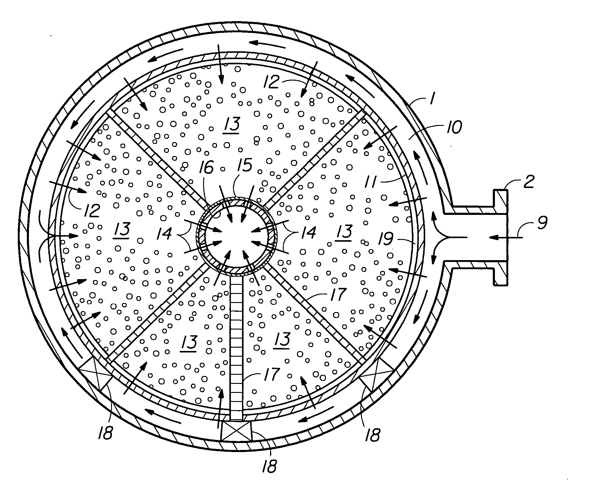
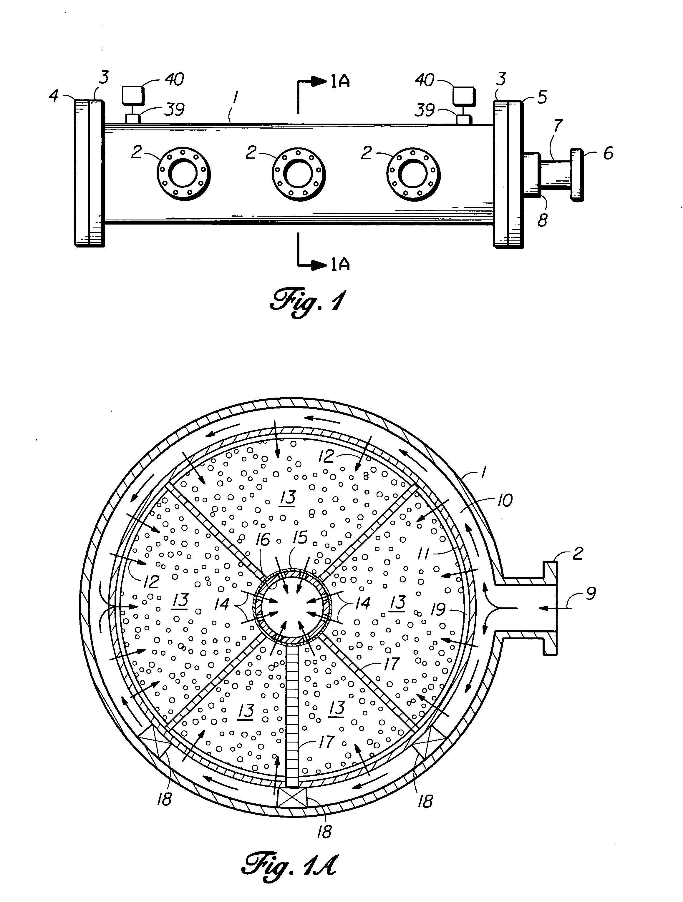
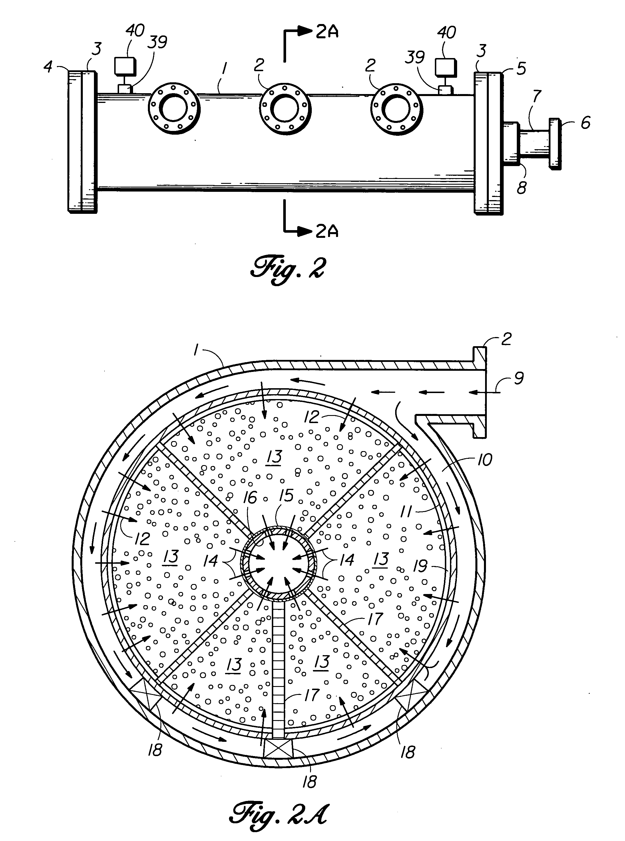
[0042] Referring now more particularly to FIG. 1, the invention's RFBC vessel assembly with outer shell 1 is shown in a first embodiment horizontal side-view position. The RFBC vessel assembly cylindrical body shell material can include either a typical example carbon steel or alloy steel pipe or rolled and welded alloy steel sheet or plate, or alternately commercially available pipe of high density polyethylene (HDPE) grade 3408 extruded pipe of appropriate diameter and SDR number. The material, diameter, and length of the RFBC vessel assembly outer shell 1 will primarily vary with the economical accommodation of desired rated gas separation capacity for each RFBC vessel assembly and the chosen operating pressure and temperature of the adsorbent or molecular sieve material employed within the selected RFBC subassembly. Typically, the RFBC vessel assembly outer shell 1 will have a length to diameter ratio of greater than 2:1.

[0043] RFBC vessel assembly shell flanged inlet gas connec...

fourth embodiment

[0069] Whereas FIG. 6 shows a single invention fourth embodiment RFBC subassembly whose total adsorbent bed as divided into two example bed segments, each hollow core cylindrical adsorbent bed segment 13 is established within the volumetric boundary formed by: (a) the combined perforated metal corrosion resistant alloy cover sheet 11 and inner surface attached corrosion resistant alloy wire mesh or other porous glass fiber or synthetic fiber based media material 19, (b) a circular metal intermediate diaphragm adsorbent support partition 35 either fastened, bonded, or fused to both perforated metal corrosion resistant alloy cover sheet 11 and the central axial core pipe or tubing 16, (c) the interior surface of end caps 20 or 21, and (d) central axial core pipe or tubing 16 and outer surface attached corrosion resistant wire mesh or other porous glass fiber or synthetic fiber based media material 15. In the case wherein the RFBC subassembly total adsorbent bed is divided into three o...


PUM

PropertyMeasurementUnit
depthaaaaaaaaaa
depthaaaaaaaaaa
diametersaaaaaaaaaa

Abstract

An improved gas separation vessel apparatus is provided. The gas separation vessel apparatus is adapted to separate oxygen and other process gases, and it employs both vertically-, or alternatively, horizontally-positioned vessels. The gas separation vessels disclosed contain removable radial-flow bed cartridge-type adsorbent subassemblies, which may be replaced, substituted, or serviced with minimal system down time.

Description

BACKGROUND [0001] 1. Field of the Invention [0002] The present invention relates generally to improved energy efficient air and process gas adsorption / desorption vessel assemblies with removable radial-flow adsorption bed cartridge subassemblies, particularly applied to VSA gas separation vessels producing a high purity oxygen gas product or other purified process product. [0003] Within the process gas industry, and in particular within the air separation market, the continuing increasing costs of electric power makes the energy efficiency of gas separation systems of ever increasing importance. The common art methods of separating a desired molecular gas from a mixture of process gases, or the separation of nitrogen from air to provide a highly predominant oxygen gaseous product stream, commonly includes the utilization of (a) power-intensive multi-stage membrane separation system, or refrigerated or cryogenic generated liquid extraction systems; (b) pressure swing adsorption (PSA)...

Claims


Application Information

Patent Timeline
Patent Type & Authority Applications(United States)
IPC IPC(8): B01D53/04
CPCB01D53/0415B01D53/0431B01D53/0476B01D2253/102B01D2259/40086B01D2253/108B01D2257/102B01D2259/40081B01D2253/104
Inventor NEARY, DAVID LLOYD
Owner AES DEV CO
Why Eureka
Try Eureka