Piezoelectric micromachined ultrasonic transducer with air-backed cavities

a micro-machined, ultrasonic transducer technology, applied in ultrasonic/sonic/infrasonic diagnostics, mechanical vibration separation, application, etc., can solve the problem of relative high resistivity polysilicon, compared, and the signal to noise ratio can be problematic during the operation of the cmut, so as to improve the impedance match, the effect of high signal to noise ratio and high bandwidth

Active Publication Date: 2006-10-26
RES TRIANGLE INST
View PDF12 Cites 89 Cited by
  • Summary
  • Abstract
  • Description
  • Claims
  • Application Information

AI Technical Summary

Benefits of technology

[0018] This invention addresses the needs for improved, smaller micromachined ultrasonic transducers and transducer arrays that have higher bandwidth, higher signal to noise ratio, better impedance match and require less energy to operate. This invention further addresses the need for a micromachined ultrasonic transducer that produces higher ultrasonic power

Problems solved by technology

One disadvantage of such a device is that relatively high resistivity polysilicon, compared to metals, is used as the conductive material in the vias.
Because of the very low signal strength (on the order of several mV or less) generated by cMUTs in the receive mode, the signal to noise ratio can be problematic during operation of the cMUT.
Also, the low capacitance of cMUT elements produces high impedance, and therefore impedance mismatch with the electronics and cabling are greater which contributes to increased signal loss and noise.
High resistance in the through-wafer vias further exacerbates the high element impedance problem.
In addition, significant resistance in the vias will cause more power consumption and heat generation during operation w

Method used


Image

  • Piezoelectric micromachined ultrasonic transducer with air-backed cavities
  • Piezoelectric micromachined ultrasonic transducer with air-backed cavities
  • Piezoelectric micromachined ultrasonic transducer with air-backed cavities

Examples


Embodiment Construction

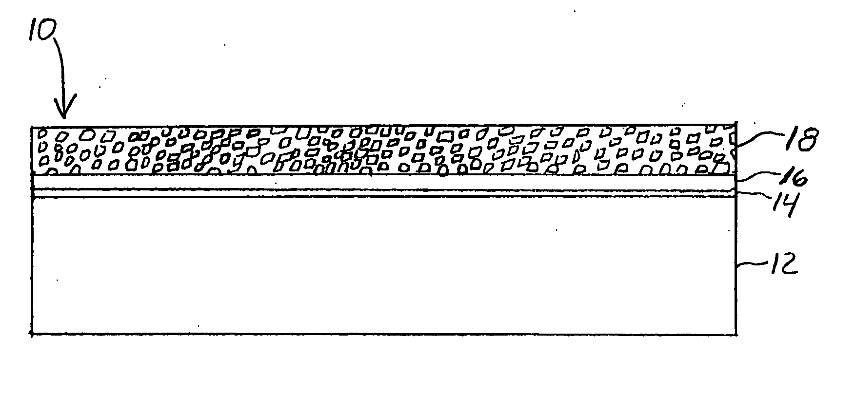
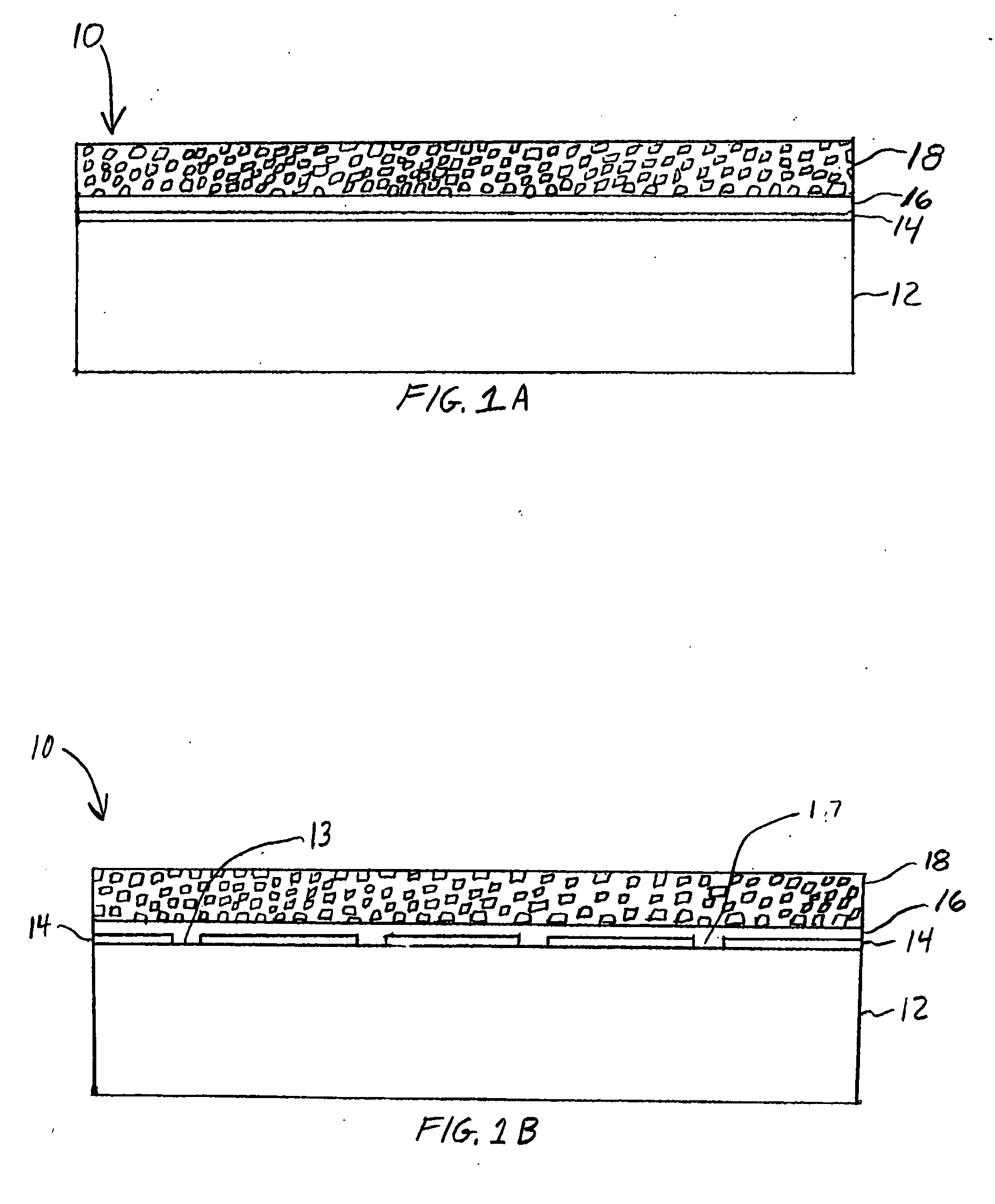
[0025] The invention will be described in conjunction with the formation of the pMUT devices illustrated in the accompanying drawings. However, this is exemplary only as the claimed invention is not limited to the formation of the specific devices illustrated in the drawings.

[0026] A method of forming a vertically integrated pMUT device according to certain embodiments of the present invention is described. A pMUT device structure 10 comprising a substrate 12 is provided, as illustrated in FIG. 1A. According to certain embodiments of the present invention, the substrate 12 is a silicon wafer. A first dielectric film 14 is formed on the substrate 12. In certain embodiments of the present invention, the first dielectric film 14 comprises silicon oxide or silicon nitride. A bottom electrode layer 16 is formed overlying the first dielectric film 14. According to certain embodiments of the present invention, the bottom electrode layer 16 can comprise a metal or conductive metal oxide. A...


PUM


Abstract

A piezoelectric micromachined ultrasonic transducer comprising a substrate and a first dielectric film formed on the substrate. An opening having a sidewall is formed through the substrate and first dielectric film. A bottom electrode is formed on the first dielectric film spanning the opening. A piezoelectric element is formed on the bottom electrode. A second dielectric film surrounds the piezoelectric element. A conformal insulating film is formed on the sidewall of the opening. A conformal conductive film is formed in contact with the bottom electrode and on the sidewall of the opening, wherein an open cavity is maintained in the opening. A top electrode is formed in contact with the piezoelectric element.

Description

TECHNICAL FIELD OF THE INVENTION [0001] This invention relates to ultrasonic transducers and in particular piezoelectric micromachined ultrasonic transducers. BACKGROUND OF THE INVENTION [0002] Ultrasonic transducers are particularly useful for non-invasive as well as in vivo medical diagnostic imaging. Conventional ultrasonic transducers are typically fabricated from piezoelectric ceramic materials, such as lead zirconate titanate (PZT), or PZT-polymer composites, with the transducer material being diced or laser cut to form a plurality of individual elements arranged in one-dimensional or two-dimensional arrays. Acoustic lenses, matching layers, backing layers, and electrical interconnects (e.g., flex cable, metal pins / wires) are typically attached to each transducer element to form a transducer assembly or probe. The probe is then connected to control circuitry using a wire harness or cable, where the cable contains individual wires to drive and receive signals from each individu...

Claims


Application Information

Patent Timeline
IPC IPC(8): H01L41/00
CPCB06B1/0622A61B8/4483H10N30/20
Inventor DAUSCH, DAVID EDWARD
Owner RES TRIANGLE INST
Why Eureka
Try Eureka