Curing composition and method for preparing same, light-shielding paste, light-shielding resin and method for producing same, package for light-emitting diode, and semiconductor device

Active Publication Date: 2006-11-02
KANEKA CORP +1
View PDF16 Cites 50 Cited by
  • Summary
  • Abstract
  • Description
  • Claims
  • Application Information

AI Technical Summary

Benefits of technology

[0408] To the curable composition and light-shielding paste of the invention, there may further be added one or more of those fillers so far used and / or proposed as the fillers in the conventional sealants, such as the epoxy-based ones, as well as colorants, mold release agents, flame retardants, flame retardant auxiliaries, surfactants, antifoaming agents, emulsifiers, leveling agents, cissing preventing agents, ion trapping agents, thixotropic agents, tackifiers, storage stability improving agents, antiozonants, light stabilizers, thickening agents, plasticizers, reactive diluents, antioxidants, heat stabilizers, electric conductivity providing agents, antistatic agents, antiradiation agents, nucleating agents, phosphorus-containing peroxide decomposers, lubricants, pigments, metal inactivators, thermal conductivity providing agents, physical property modifiers and so forth, each within the range within which the object and effect of the invention will not be defeated or weakened.

Problems solved by technology

Since, on the other hand, the package is generally made of an organic resin, continued irradiation of the sidewalls with light causes problems, for example a decrease in adhesion to the sealing member due to deterioration of the package resin, a decrease in reflectivity due to discoloration of the package resin and the resulting decrease in brightness of the LED.
From the optical characteristics viewpoint, however, the materials obtained by this technology are not suited for use as the light-shielding resins for light-emitting diodes.
However, there is no disclosure therein about such light-shielding resins for light-emitting diodes.
However, this system is a room temperature curing one, and there is no disclosure either about effect manifestation upon heating for curing or about effect manifestation in the case of application to addition reaction type systems differing therefrom in mode of reaction.
However, there is no disclosure about the adhesion after light irradiation, which is required of light-shielding resins for light-emitting diodes.
Meanwhile, the light-shielding layers can indeed be formed by curing a curable composition but there is a problem in that when the curable composition is high in flow leveling property, it flows onto the package bottom during curing, leading to failure to obtain light-shielding layers having a desired thickness.
When the curable composition is high in flow leveling property, another problem arises, namely the bottom is stained and, for example, it becomes impossible to gain electric access to lead frame members disposed on the bottom.
Furthermore, it is also a problem that no effective method is available to coat the LED package aperture sidewalls alone.

Method used


Image

  • Curing composition and method for preparing same, light-shielding paste, light-shielding resin and method for producing same, package for light-emitting diode, and semiconductor device
  • Curing composition and method for preparing same, light-shielding paste, light-shielding resin and method for producing same, package for light-emitting diode, and semiconductor device
  • Curing composition and method for preparing same, light-shielding paste, light-shielding resin and method for producing same, package for light-emitting diode, and semiconductor device

Examples


synthesis example 1

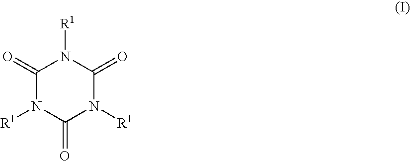
Synthesis of triallyl isocyanurate-1,3,5,7-tetramethylcyclotetrasiloxane Reaction Product, which is a Component (B)

[0460] A 5-L separable flask was charged with 1.8 kg of toluene and 1.44 kg of 1,3,5,7-tetramethylcyclotetrasiloxane, and heated until the inside temperature arrived at 104° C. Thereto was added dropwise a mixture of 200 g of triallyl isocyanurate, 1.44 mL of a xylene solution of platinum-vinylsiloxane complex (containing 3% by weight of platinum) and 200 g of toluene. The resulting mixture was heated under reflux in an oil bath at 120° C. for 7 hours. Then, 1.7 g of 1-ethynyl-1-cyclohexanol was added. The unreacted portion of 1,3,5,7-tetramethylcyclotetrasiloxane and the toluene were distilled off under reduced pressure. 1H-NMR revealed that the product was the reaction product resulting from part of the SiH groups of 1,3,5,7-tetramethylcyclotetrasiloxane with triallyl isocyanurate (hereinafter referred to as partial reaction product B1, SiH value: 8.2 mmol / g, allyl v...

example 4

[0464] The light-shielding pastes obtained in Examples 1 to 3 were each applied onto a polyphthalamide resin molding while controlling the film thickness using a tape as a spacer, and then cured at 100° C. for 1 hour to form a light-shielding layer. A die for die shear testing was bonded to each light-shielding layer with an adhesive prepared in the manner mentioned below.

[0465] The adhesive layer was formed by heating at 60° C. for 6 hours, 70° C. for 1 hour, 80° C. for 1 hour, 120° C. for 1 hour, 150° C. for 1 hour and 180° C. for 30 minutes, in that order, followed by curing.

example 1

MEASUREMENT EXAMPLE 1

[0471] The test specimens obtained in Example 4 and Comparative Example 1 were evaluated for adhesion by die shear testing. Used as the die shear tester was Dage's multi-purpose bondtester 2400. The temperature was 23° C., a 50-kgf load cell was used, and the testing speed was 83 μm / sec. The results obtained are shown in Table 1.


PUM

PropertyMeasurementUnit
Temperatureaaaaaaaaaa

Abstract

The invention aims at providing A light-shielding paste which contains a thermoplastic resin and an inorganic member as essential components; A light-shielding paste which contains a thermosetting resin and an inorganic member as essential components; A curable composition which contains, as essential components, (A) an organic compound comprising an organic main chain containing at least two carbon-carbon double bonds reactive with a SiH group in each molecule, (B) a silicon compound having at least two SiH groups in each molecule, (C) a hydrosilylation catalyst, (D) a silane coupling agent and / or an epoxy group-containing compound, (E) a silanol condensation catalyst, and (F) an inorganic member; The above curable composition which further contains (G) silica; The above curable composition which shows such a flow leveling property that when the composition is allowed to stand on a glass substrate inclined at an angle of 80 degrees at 100° C. for 1 hour, the flow-out distance is not longer than 2 cm; A light-shielding paste which comprises the above curable composition; or, A method of forming a light-shielding resin layer on a LED package having an aperture comprising a bottom and sidewalls and formed of a molding resin by a monolithic process with the respective ends of an external positive electrode and an external negative electrode being exposed at a predetermined distance on the aperture bottom which method comprises (1) applying a light-shielding paste to a substrate; (2) bringing the LED package aperture into close contact therewith; and (3) heating the LED package with the aperture facing upward; and thereby the light-shielding paste is allowed to spread along the package sidewalls alone. The curable composition of the invention is excellent in light-shielding ability and is highly resistant to light and, therefore, can be used as a light-shielding paste. Further, the curable composition of the invention is low in fluidity and, therefore, light-emitting diodes with the curing product formed on the LED package sidewalls alone can be obtained by using that curable composition. Furthermore, according to the method of light-shielding resin layer formation according to the invention, it is possible to efficiently apply a light-shielding paste to the LED package sidewalls alone for light-shielding resin layer formation, whereby the productivity is markedly improved.

Description

TECHNICAL FIELD [0001] The present invention relates to a curable composition, a method of preparing curable compositions, a light-shielding paste, a light-shielding resin resulting from curing of such a light-shielding paste, a method of forming light-shielding resins, a light-emitting diode package covered with a light-shielding resin, and a light-emitting diode as a semiconductor device. More particularly, it relates to a curable composition excellent in adhesive properties and having high light-shielding ability, preferably a curable composition which is, in addition, low in flow leveling property and adequate in workability. It also relates to a method of efficiently forming a light-shielding resin layer on the LED package aperture sidewalls alone, and a light-emitting diode with a light-shielding layer formed on the LED package aperture sidewalls alone. BACKGROUND ART [0002] With the recent enlargement of the field of applications of light-emitting diodes (hereinafter also ref...

Claims


Application Information

Patent Timeline
IPC IPC(8): C09K19/52C08K3/22C08L83/04C08L101/00C09D7/80C09D183/05H01L23/29H01L33/44
CPCC08F283/00C08F290/06H01L2924/0002H01L2924/12044H01L33/44H01L23/295C08L101/00C08F290/14C08G77/452C08G77/485C08G77/54C08K3/22C08L51/003C08L53/00C08L83/04C08L2666/02H01L2924/00Y10T428/31663Y10T428/31786
Inventor TSUMURA, MANABUIDE, MASAHITOOUCHI, KATSUYAKURAMOTO, MASAFUMIMIKI, TOMOHIDE
Owner KANEKA CORP
Why Eureka
Try Eureka