

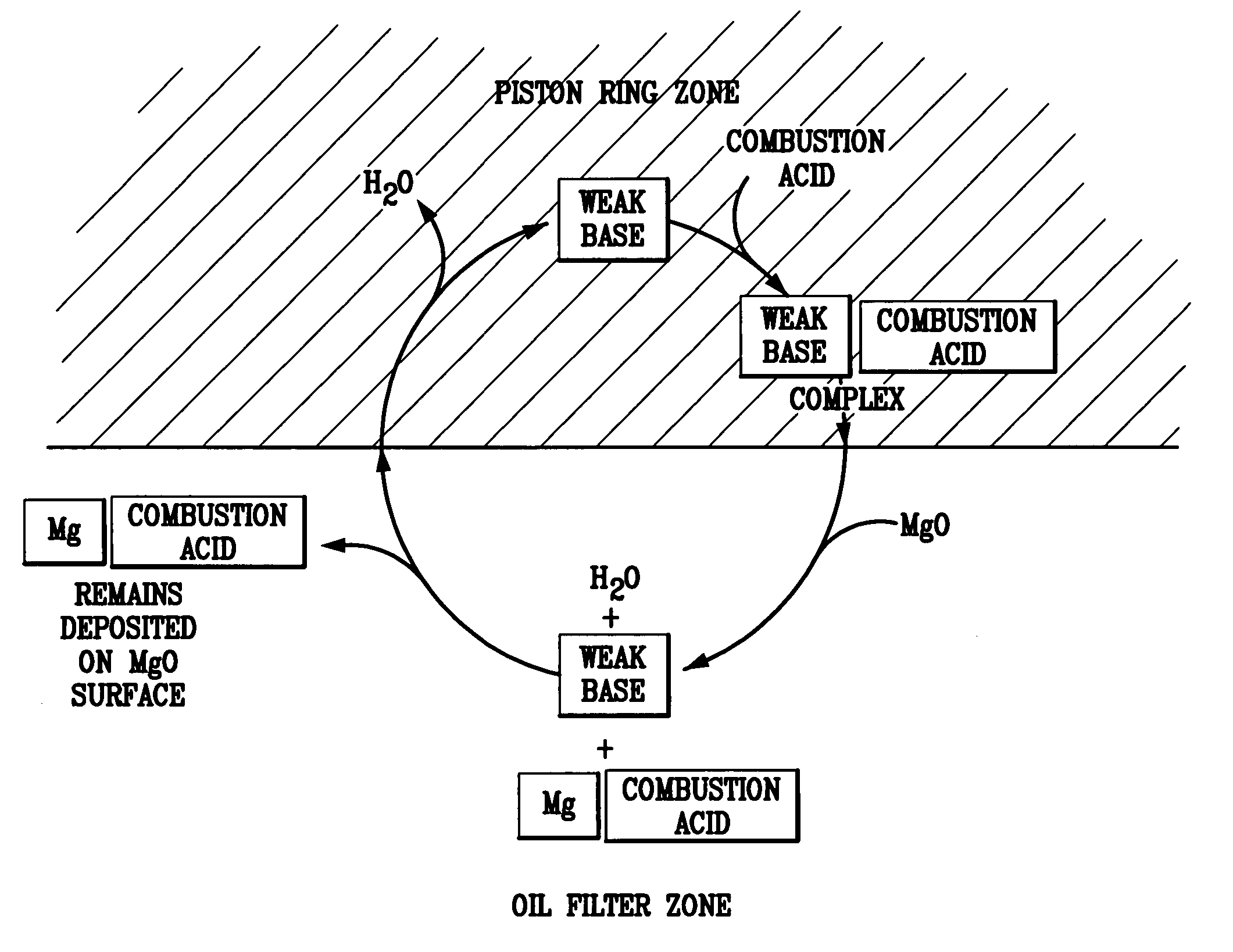
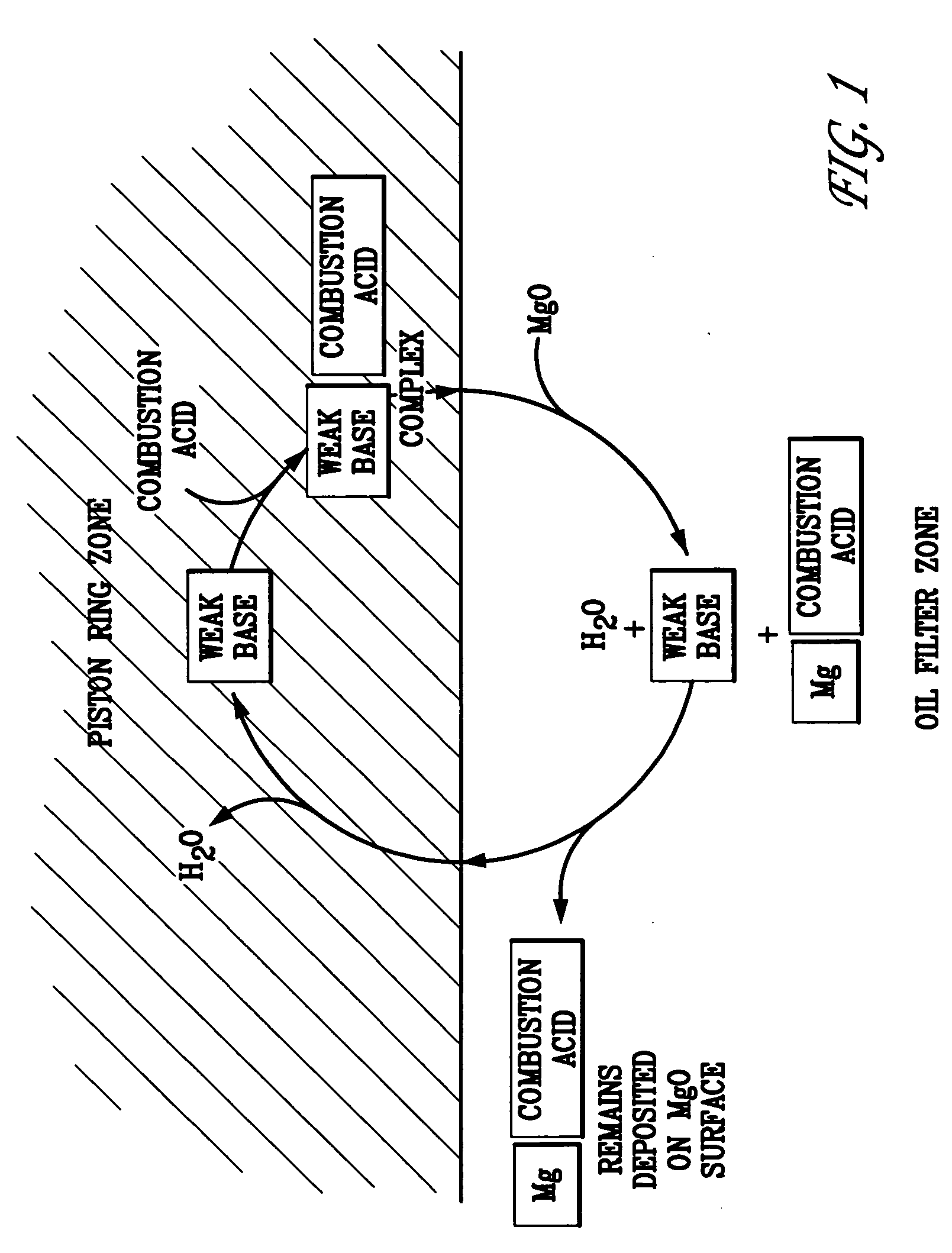
Materials, filters, and systems for immobilizing combustion by-products and controlling lubricant viscosity
a technology of combustion by-products and material filters, applied in the field of chemical filters, can solve the problems of engine wear, extreme high gas pressure, formation of contaminants, etc., and achieve the effect of prolonging the interval between oil drains and maximizing exchange capacity
- Summary
- Abstract
- Description
- Claims
- Application Information
AI Technical Summary
Benefits of technology
Problems solved by technology
Method used
Image

Examples
examples
[0096] Several candidate strong base materials were investigated for suitable application in chemical filters of the present invention. Gas adsorption and mercury porosimetry methodologies were utilized to characterize the porosity and surface area characteristics of the candidate materials, as described below.
[0097] In order to ensure that all porosity is accurately accounted and measured, formed, bound, or solid materials must be ground into a fine powder whose particle size is that of the primary particles before running the pore analysis. To determine whether or not the transformed material is sufficiently ground prior to assessing its porosity, electronic micrograph results of the ground material can be compared to the porosimetry results. The transformed material is sufficiently ground when the electron micrograph results indicate pores sizes substantially equivalent to the pore sizes measured via porosimetry techniques. This sample preparation is intended...
PUM
| Property | Measurement | Unit |
|---|---|---|
| Pore size | aaaaa | aaaaa |
| Pore size | aaaaa | aaaaa |
| Pore size | aaaaa | aaaaa |
Abstract
Description
Claims
Application Information