Optical system and optical microscope
- Summary
- Abstract
- Description
- Claims
- Application Information
AI Technical Summary
Benefits of technology
Problems solved by technology
Method used
Image

Examples
first embodiment
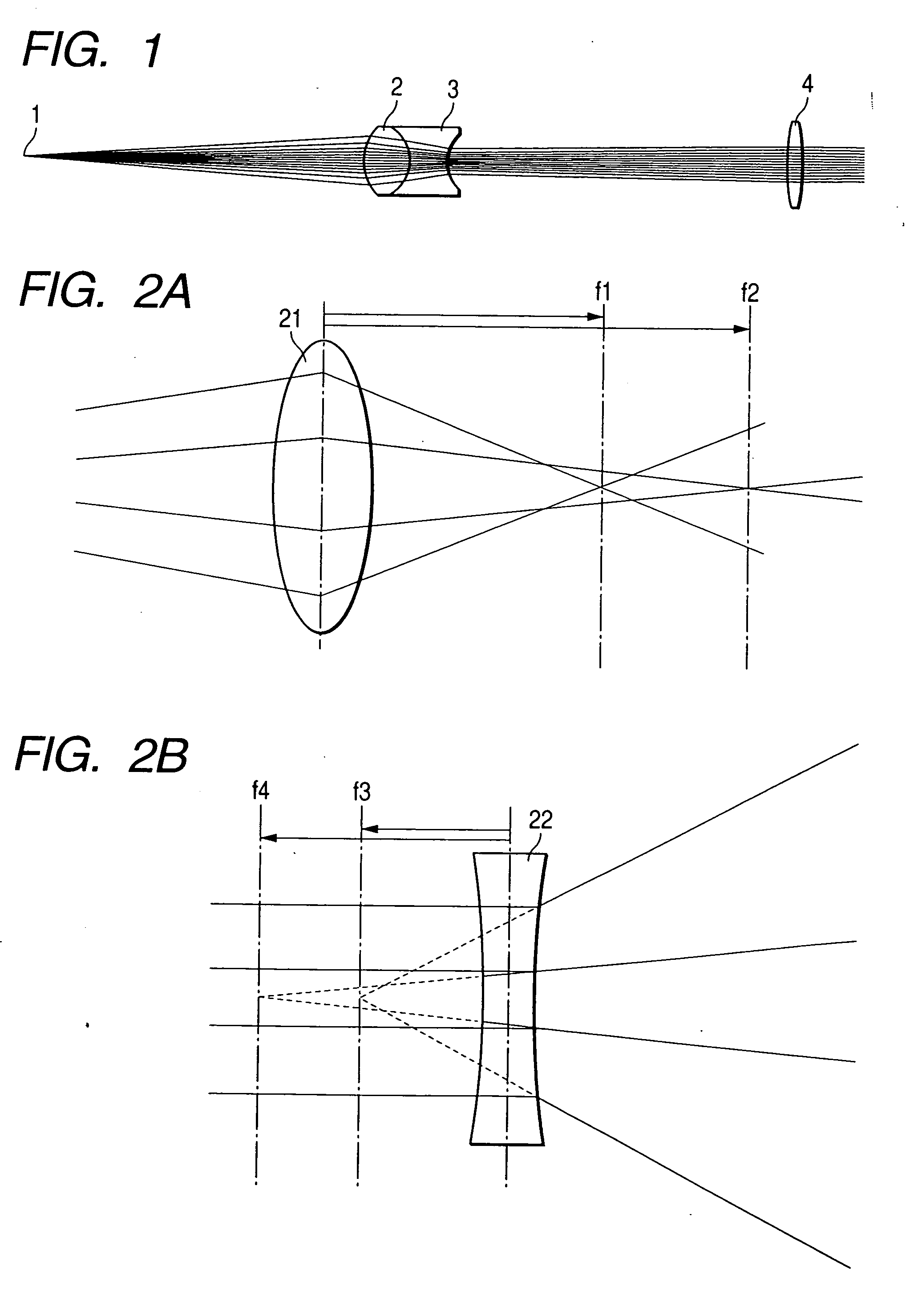
[0051] Hereinafter, the invention will be described in detail with reference to the accompanying drawings. FIG. 1 is a diagram showing a light intensity distribution correcting optical system of the invention. The optical system of the embodiment is placed instead of the collimating lens and the light intensity uniformalizing lens of the confocal microscope described as the related example (FIG. 6).
[0052] Referring to FIG. 1, a light source 1 is a point light source such as a semiconductor laser diode (hereinafter, abbreviated as LD), a light emitting diode (hereinafter, abbreviated as LED), or an end face of an optical fiber, and emits divergent light. A first convex lens 2 refracts the divergent light from the light source 1 toward the optical axis by the positive refracting power to cause the light to be incident on a concave lens 3 while the beam diameter is reduced. The concave lens 3 refracts the light emitted from the first convex lens 2 toward the outside by the negative ref...
second embodiment
[0070]FIGS. 4A and 4B are diagrams showing a light intensity distribution correcting optical system of the invention. The optical system of the embodiment is placed instead of the collimating lens and the light intensity uniformalizing lens of the confocal microscope described as the related example (FIG. 6).
[0071]FIG. 4A is a plan view, and FIG. 4B is a side view.
[0072] Referring to FIGS. 4A and 4B, a first cylindrical lens 42 has a short focal length f5, and a second cylindrical lens 43 has a long focal length f6. The light emission face of an LD 41 is located at a position corresponding to the focal lengths of the cylindrical lenses. The cylindrical lenses are rotated by 90° with respect to each other. This configuration is employed in order to use a characteristic in which light is refracted because a cylindrical lens has a curvature in a sectional direction along which the lens can be seen to be semicircular, and light is passed straight through the lens because the lens has n...
PUM
 Abstract
Description
Claims
Application Information
 - Generate Ideas
- Intellectual Property
- Life Sciences
- Materials
- Tech Scout
- Unparalleled Data Quality
- Higher Quality Content
- 60% Fewer Hallucinations
Browse by: Latest US Patents, China's latest patents, Technical Efficacy Thesaurus, Application Domain, Technology Topic, Popular Technical Reports.
© 2025 PatSnap. All rights reserved.Legal|Privacy policy|Modern Slavery Act Transparency Statement|Sitemap|About US| Contact US: help@patsnap.com