
Decorated plastic package and method for reproduction

a plastic package and reproduction technology, applied in the field of colored plastic package, a method for decorating, and a reproduction method, can solve the problems of difficult recycling of colored package, limited penetration of wavelength components of light absorbed by coloring components into the containers, and high cost, so as to promote recycling and reduce the ratio of containers

Inactive Publication Date: 2006-11-23
TOYO SEIKAN KAISHA LTD
View PDF11 Cites 30 Cited by
  • Summary
  • Abstract
  • Description
  • Claims
  • Application Information

AI Technical Summary

Benefits of technology

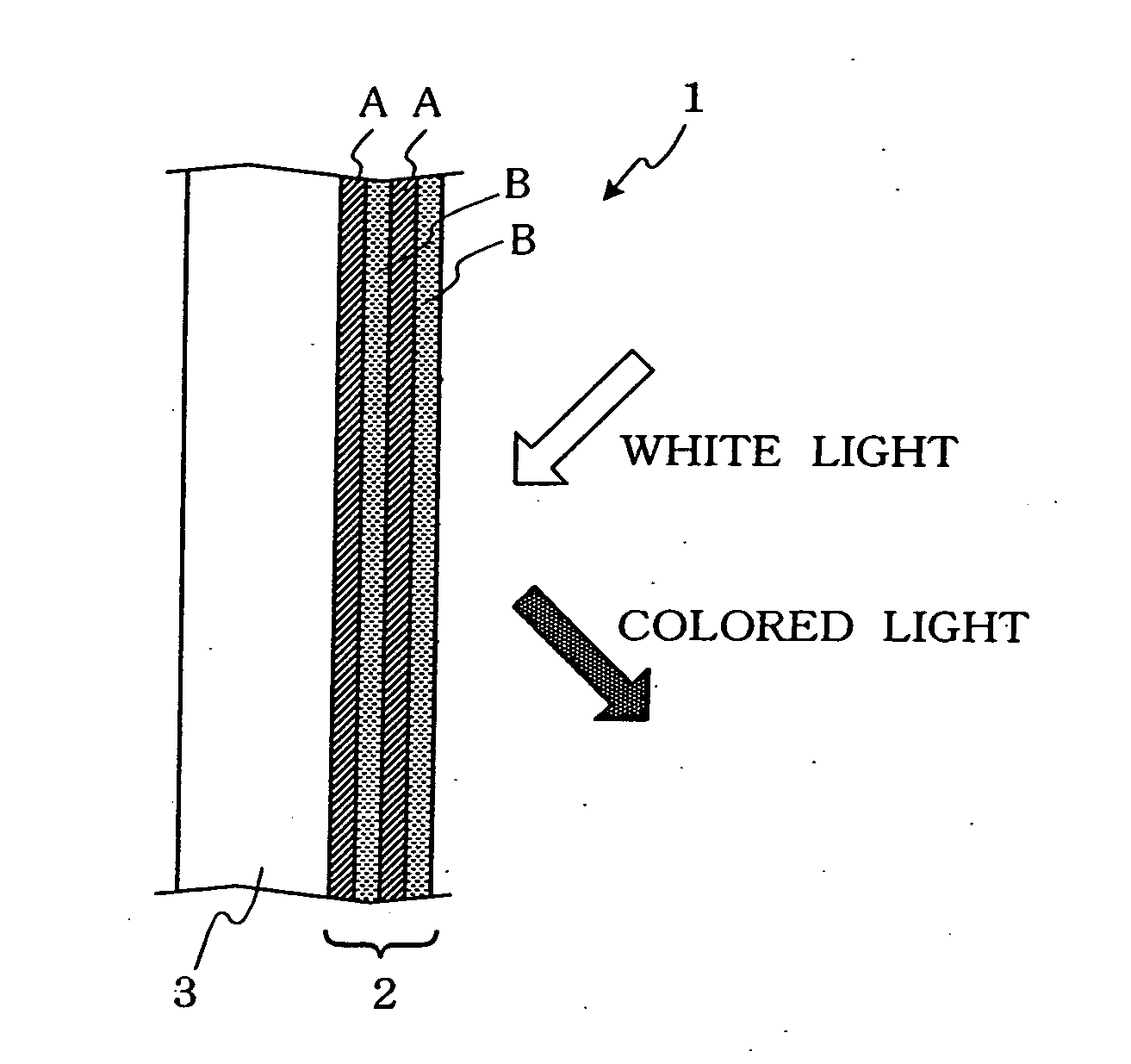
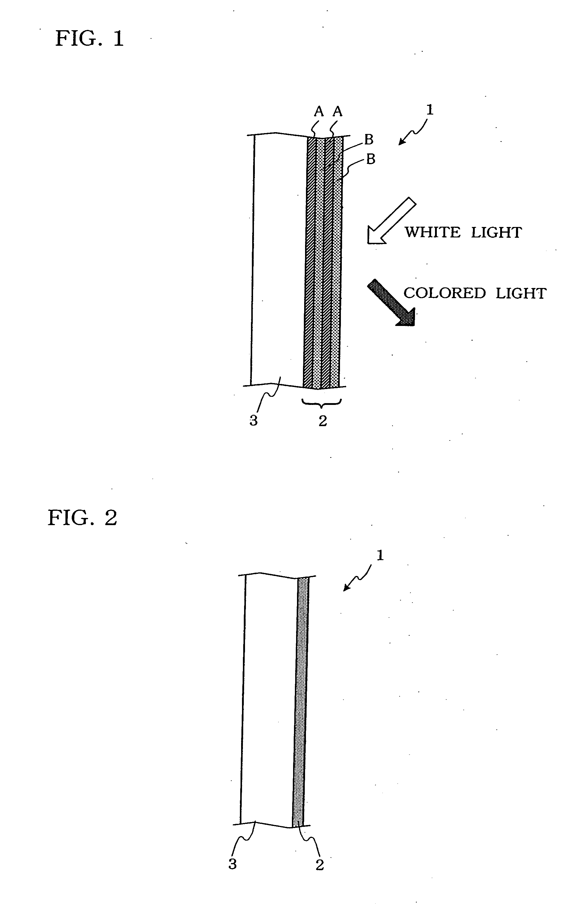
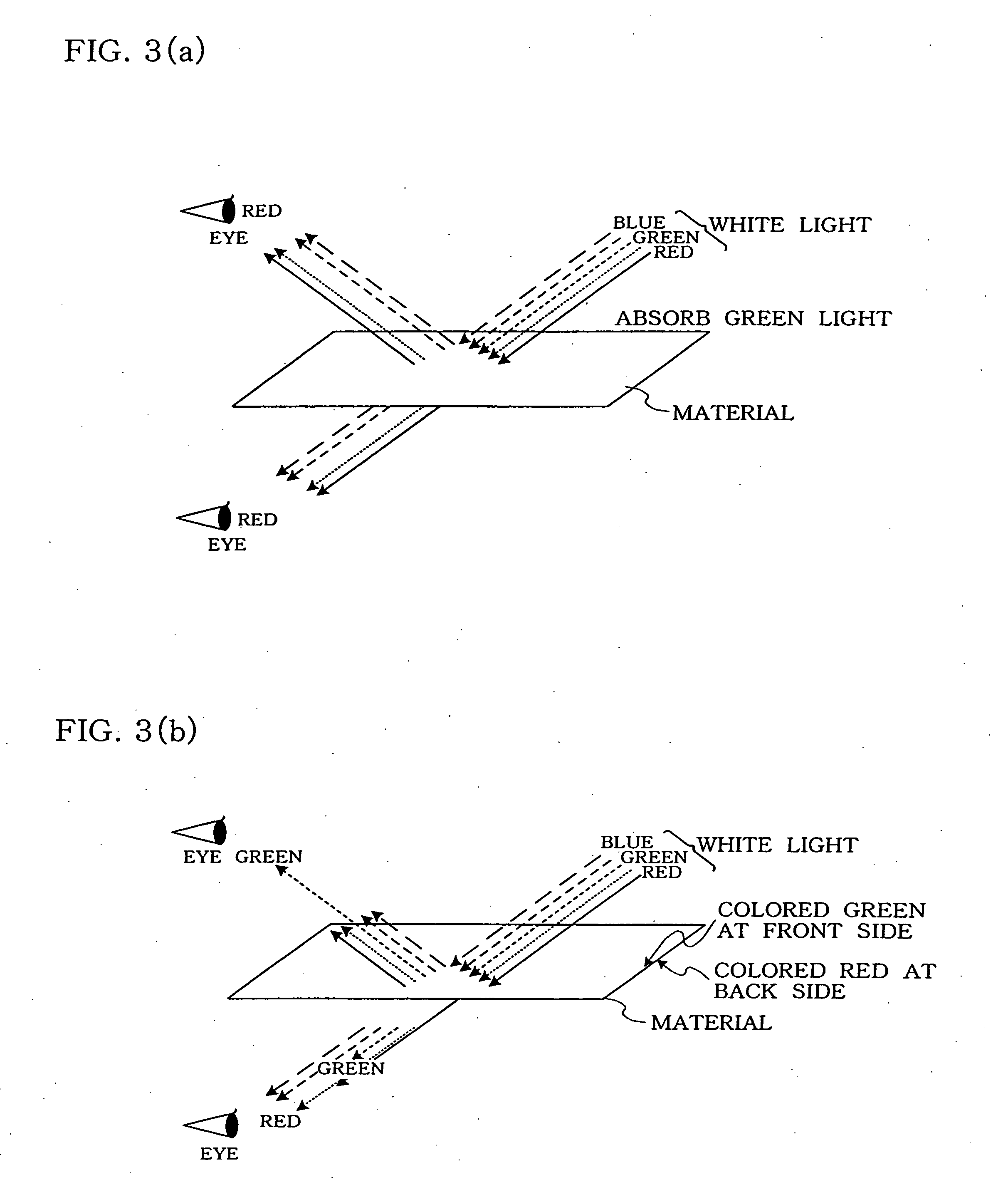
[0037] In order to achieve the object, the present inventors have found that a package containing a thin-film layered structure comprising substances having different refractive indices and colored by an interference effect due to the thin-film layered structure or a plastic package which develops color by forming a fine periodically arranged structure which is different in optical characteristics on the surface of the package can be easily decolored by heating in a reproduction step and is excellent in recycle properties. Thus, they have accomplished the present invention.

Problems solved by technology

With these containers, penetration of the wavelength components of the light which is absorbed by coloring components into the containers is restricted, and in consequence, the protection of the contents that are apt to change in quality or to deteriorate owing to a light beam, i.e., visible light barrier performance, is imparted.
In recent years, however, from the viewpoints of the saturation of landfill sites and resource saving, the recycle of resins has been promoted, but it is difficult to reuse the colored packages.
Therefore, in the case of the PET bottles colored with colorant constituted of conventional chemical substances, it is difficult to decolor them, which makes their recycle severe.
Although this problem is common to the whole plastic packages, it is particularly serious for the PET bottle because of its amount of usage.
In the package, however, a large amount of a mica / titanium pigment or the like is used as the scaly thin film, and hence, separation of the material is necessary during the recycle, which still makes their recycle severe.
Therefore, the above method of the coloration by the physical coloring mechanism is not allowed in a flow of the present recycle, as in the case of the above method by the chemical coloring mechanism.
However, since the transparent container must involve the laminate film therein, this technology is limited to bottles having a mouth part of an inside diameter smaller than that of the body part.
Therefore, it is impossible to apply the technology to cups, trays, and the like molded from plastics.
In addition, since the laminate film is in contact with contents, there arises a hygienic problem in a case where the contents are foods.
Therefore, there is a problem that the packages once colored cannot be remanufactured in the form of the transparent packages.
Therefore, there arises a problem that the colored PET bottles cannot be used as starting materials for the PET bottles to be re-manufactured.
If the trial bottles are contaminated with a pigment or a dye, they remain colored with the pigment or the like even at a stage where they are molded into the reproduced pellets, and hence, they do not satisfy the evaluation standards of “the color tone”.
In addition, the color of the trial bottles still remains even at a stage where they are molded into the fibers, the bottles or the sheets, and therefore, the evaluation standards of “the color tone” are not satisfied herein, either.
As described above, the PET bottles mixed with the pigment or the dye do not satisfy the material evaluation standards, and for this reason, they cannot be used as starting materials for the reproduction.

Method used


Image

  • Decorated plastic package and method for reproduction
  • Decorated plastic package and method for reproduction
  • Decorated plastic package and method for reproduction

Examples


first embodiment

[0141] FIGS. 5 to 7 are drawings for illustrating a first embodiment of the method for forming a periodically arranged structure different in optical characteristics.

[0142] In the present embodiment, a periodically arranged structure is formed on a plastic bottle container utilizing a diffraction phenomenon of a laser light.

[0143] In this method, a laser source 11, a lens 12, and a diffraction grating 13 are used.

[0144] The laser source 11 oscillates a laser light and, for example, carbon dioxide gas laser, YAG laser, semiconductor laser, helium-neon or argon gas laser, excimer laser, and the like can be used. In addition, those whose wavelengths are converted into these laser lights can be also used.

[0145] The laser light may be used in a continuous oscillation state or in a pulse oscillation state.

[0146] The lens 12 is used for converting the laser light oscillated from the laser source 11 into a parallel ray.

[0147] The diffraction grating 13 diffracts the laser light. For e...

second embodiment

[0156]FIG. 8 is a drawing for illustrating a second embodiment of the method for forming a periodically arranged structure different in optical characteristics.

[0157] In the present embodiment, a periodically arranged structure is formed on a plastic bottle container utilizing refraction and convergence of a laser light.

[0158] In the present embodiment, fine concavities and convexities 19 having a lens effect are formed on a wall 15 of a plastic bottle container 14.

[0159] The concavities and convexities 19 can be formed, for example, by forming concavities on the surface of a blow mold, and transferring the shape from the mold to the container wall during a thermal treatment in the molding step of the above plastic bottle container.

[0160] When the concavities and convexities 19 formed on the wall 15 of the plastic bottle container are irradiated with a laser light as in the first embodiment, as shown in FIG. 8, the laser light is refracted by a lens effect of the concavities and...

third embodiment

[0164]FIG. 9 is a drawing for illustrating a third embodiment of the method of forming a periodically arranged structure different in optical characteristics.

[0165] In the present embodiment, light / heat-absorbing fine particles 20 which are to be nuclei of heat generation are mixed and dispersed into a main material resin of a plastic bottle container 14, and then molding of the container is achieved.

[0166] The light / heat-absorbing fine particles are fine particles which react with a specific laser light to generate heat. For example, there may be mentioned mica, kaolin, talc, titanium oxide-coated mica, and the like.

[0167] The particle size of the light / heat-absorbing fine particles is from 0.1 μm to 100 μm. When the size is larger than 100 μm, there is a risk that a resin becomes opaque when mixed therewith. Preferably, the size is from 0.2 μm to 30 μm.

[0168] The light / heat-absorbing fine particles 20 may be mixed with the whole of the plastic bottle container (preform) but ma...


PUM

PropertyMeasurementUnit
thicknessaaaaaaaaaa
wavelength rangeaaaaaaaaaa
thicknessaaaaaaaaaa

Abstract

There is here disclosed a plastic package (1) which has a thin-film layered structure (2) constituted of substances having different refractive indices and which is colored by an interference effect due to the thin-film layered structure (2). The plastic package is characterized in that, on a part of the surface of the plastic package, portions which are different in optical characteristics from the surface are periodically arranged.

Description

TECHNICAL FIELD [0001] The present invention relates to a colored plastic package, a method for decorating, and a method for reproduction. More particularly, it relates to a plastic package which maintains coloration when used as a package but can easily be decolored by external stimulation during reproduction, and a method for reproduction thereof. BACKGROUND ART [0002] Plastics are suitable for mass production because of easy molding. Moreover, since the plastics possess excellent physical properties such as transparency and impact resistance, they have been widely used as various kinds of packages such as bottle containers, cups, pouches, and packaging sheets. [0003] These packages are packed with various kinds of drinks, seasonings, cosmetics, drugs and the like as contents. However, some of these contents change in quality or deteriorate by a light, and therefore, for the purpose of protecting such contents from the light, the packages are colored in some cases. Furthermore, in...

Claims


Application Information

Patent Timeline
Patent Type & Authority Applications(United States)
IPC IPC(8): B32B27/08B32B7/023B65D1/02B65D65/40
CPCB32B1/02Y10T428/13B32B7/02B32B27/08B32B27/18B32B27/32B32B27/34B32B27/36B32B2250/24B32B2250/42B32B2307/4026B32B2307/41B32B2307/412B32B2307/418B32B2307/558B32B2307/704B32B2439/06B32B2439/60B32B2553/00B65D1/0215B32B33/00B32B38/06B32B2037/148B32B2307/402B44C1/228Y10T428/24942Y10T428/1352Y10T428/1379B32B3/26B32B7/023B32B1/00B44C1/005B44C1/18B44C1/22G02B1/04G02B3/0012G02B6/0065
Inventor YAMADA, TOSHIKITAKENOUCHI, KENKIKUCHI, ATSUSHI
Owner TOYO SEIKAN KAISHA LTD
Learn More