Environmental control in a reticle SMIF pod

a technology of reticle and environment control, applied in the field of smif, can solve the problems of damage to delicate features, contamination and damage of reticles used in euv photolithography, and the art does not provide transparent pellicle materials, so as to achieve the effect of regenerating the filter

Active Publication Date: 2006-11-30
ENTEGRIS INC
View PDF17 Cites 51 Cited by
  • Summary
  • Abstract
  • Description
  • Claims
  • Application Information

AI Technical Summary

Benefits of technology

[0011] According to another aspect of the present invention, the filter media is selected to weakly bind to the contaminants so that the contaminants could be expelled from the filter by subjecting the filter to a flow of pressurized gas thereby regenerating the filter.
[0012] According to a related embodiment of the present invention, the filter is shaped, sized and located so as to present a surface on which particulates will preferentially settle instead of settling on the patterned surface of the reticle. Another aspect of the alternate embodiment contemplates a large filter, i.e. a filter with at least one major surface are that is preferably at least sixty percent of the surface area of the patterned surface, to take advantage of the diffusion length of the particulates within the container to cause the particulates to preferentially settle on the filter as opposed to settling on the patterned surface of the reticle. According to another aspect of the primary embodiment, the filter is preferably shaped and sized substantially proportionate to the reticle and preferably positioned substantially concentrically with respect to the reticle. One aspect of this embodiment at least one surface of the filter is disposed substantially to the carrier door portion with the reticle residing on the reticle supports.
[0013] According to a related embodiment, the present in...

Problems solved by technology

At his time, the art does not provide pellicle materials that are transparent to EUV.
Consequently, the reflective photomask (reticle) employed in EUV photolithography is susceptible to contamination and damage to a far greater degree than reticles used in conventional photolithography.
It is well known in the art that unnecessary and unintended contact of the reticle with other surfaces during manufacturing, processing, shipping, handling, transport or storage will likely cause damage to the delicate features on the patterned surface of the reticle due to sliding friction and abrasion.
Likewise, it is generally accepted by those skilled in the art that any particulate contamination of the surface of the reticle can potentially compromise the reticle to a degree sufficient -to seriously affect the end products of processes that use such a flawed reticle.
For example, thin walled SMIF pods may experience wall movement due to altitude related pressure changes causing the trapped air inside the controlled environment to be displaced.
Dimensional changes of the container and its components due to pressure fluctuations can lead to compromising the sealing between cover and door of the carrier and incursion of particulates within the carrier.
Even with a perfectly seal...

Method used


Image

  • Environmental control in a reticle SMIF pod
  • Environmental control in a reticle SMIF pod
  • Environmental control in a reticle SMIF pod

Examples


Embodiment Construction

[0028] The accompanying Figures depict embodiments of the reticle carrier of the present invention, and features and components thereof. Any references to front and back, right and left, top and bottom, upper and lower, and horizontal and vertical are intended for convenience of description, not to limit the present invention or its components to any one positional or spatial orientation. Any dimensions specified in the attached Figures and this specification may vary with a potential design and the intended use of an embodiment of the invention without departing from the scope of the invention.

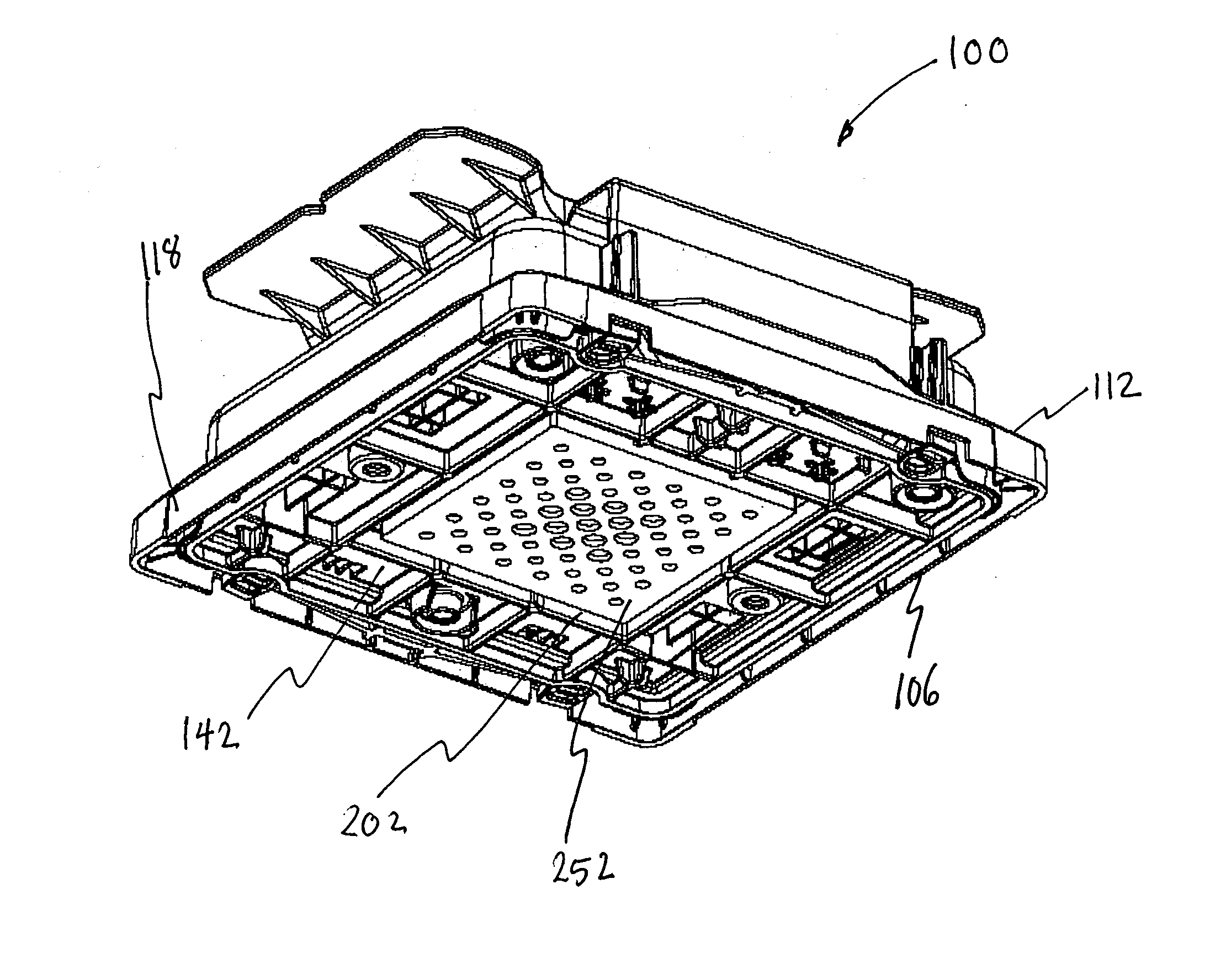
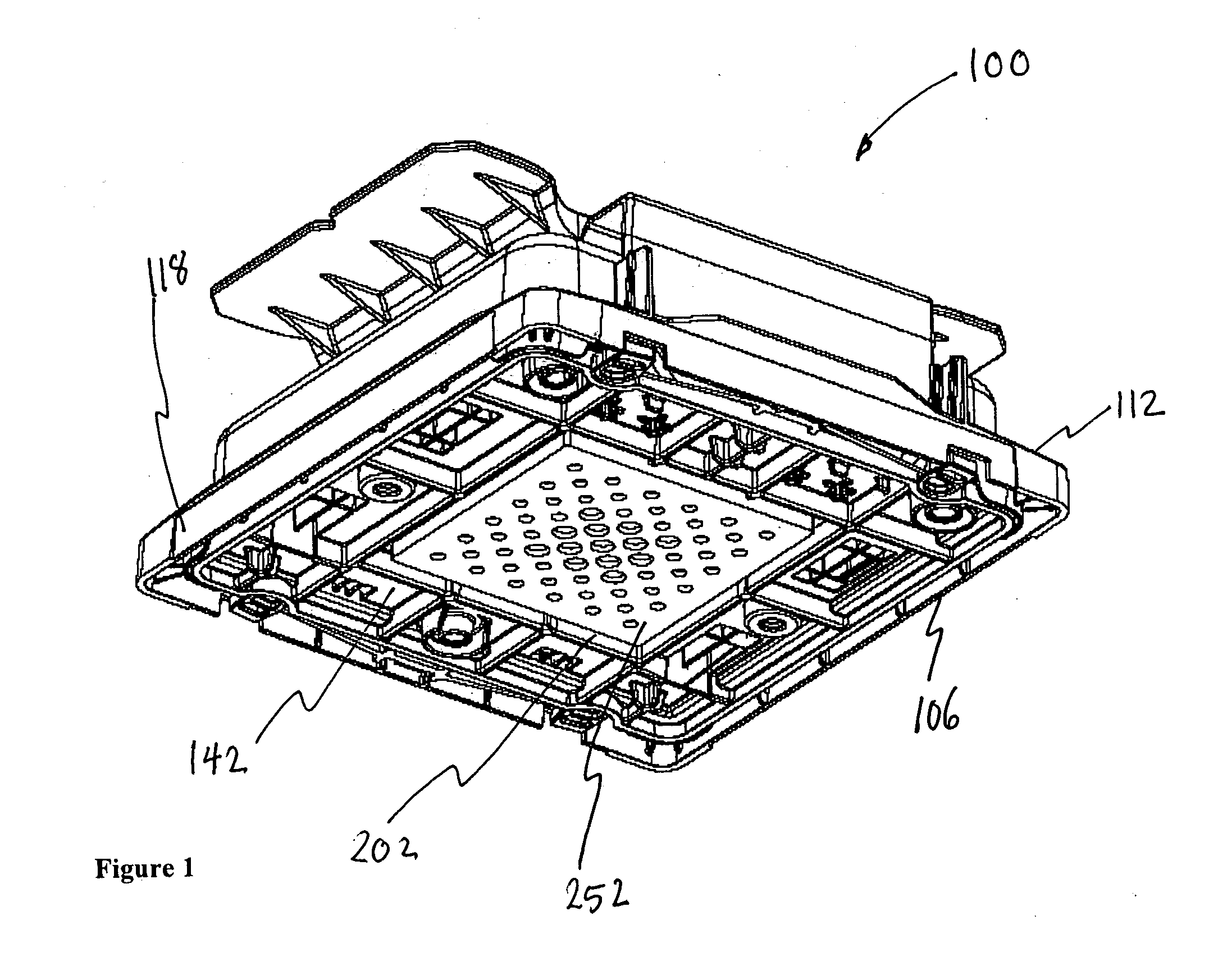
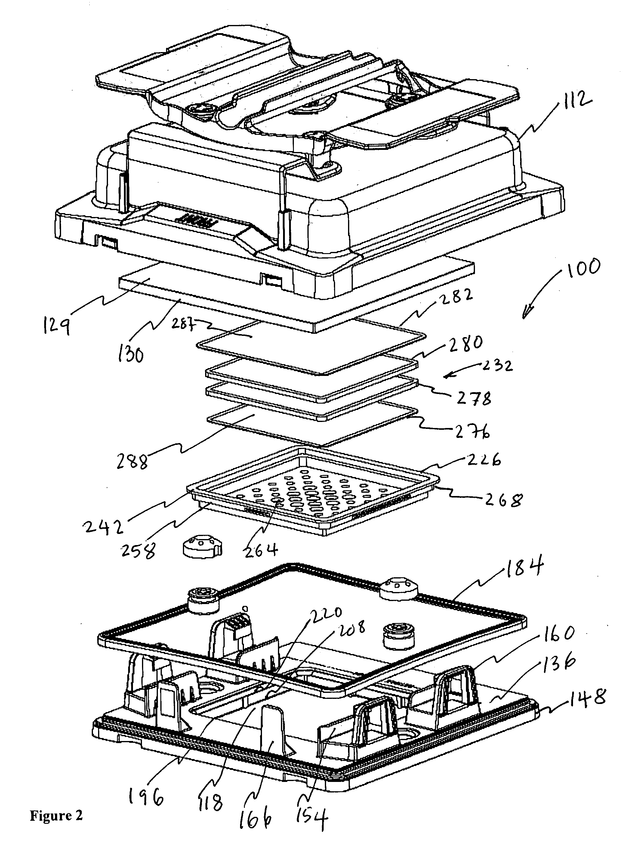
[0029] In FIGS. 1-11, there is shown a reticle carrier 100 equipped with a chemical filtration system according to a primary embodiment of the present invention. The reticle carrier 100 (alternatively referred to as a reticle container, a reticle pod, or a reticle box) generally comprises a door portion 106 (alternatively referred to as a base portion) which mates with a carrier shell 112 (a...


PUM

PropertyMeasurementUnit
Fractionaaaaaaaaaa
Fractionaaaaaaaaaa
Concentrationaaaaaaaaaa

Abstract

The present invention provides a standardized mechanical interface (SMIF) reticle pod that is configured to provide a controlled environment for supporting a reticle wherein the controlled environment is maintained substantially free of crystal growth causing contaminants. Accordingly, there is provided a layered filter with filter elements capable of filtering particulates and adsorbing gaseous contaminants. The filter has an inwardly facing face generally planar shaped with a surface area that is substantially half or more of the area of the reticle face. The inwardly facing face is placed in close proximity to the reticle patterned surface and has an area that is a significant fraction of the reticle patterned surface area. The SMIF pod is also provided with a purge system configured to inject a very dry gas within the controlled environment to flush the controlled environment of contaminants as well as to regenerate the filter.

Description

RELATED APPLICATION [0001] The present application claims the benefit of U.S. Provisional Application No. 60 / 668,189 filed Apr. 4, 2005, which is incorporated herein in its entirety by reference.FIELD OF THE INVENTION [0002] The invention relates to standardized mechanical interface (SMIF) substrate carriers used in semiconductor manufacturing and more particularly to transportable and shippable reticle / photomask carriers that include a filtration system to reduce chemical and particulate contaminants within the controlled environment of the carrier. BACKGROUND OF THE INVENTION [0003] The processing of silicon wafers for semiconductor applications typically includes photolithography as one of the process steps. In photolithography, a wafer surface with a deposit of silicon nitride is coated over with a light-sensitive liquid polymer or photoresist and then selectively exposed to a source of radiation using a template with a desired pattern. Typically, ultraviolet light is shone thro...

Claims


Application Information

Patent Timeline
IPC IPC(8): B01D50/00
CPCH01L21/67389H01L21/67393H01L21/67386H01L21/67353H01L21/67359H01L21/67017B01D47/12B03C3/00H01L21/673B01D50/00
Inventor HALBMAIER, DAVID L.SIMPSON, ANTHONYGOODWIN, WILLIAM M.KISHKOVICH, OLEG P.KIELBASO, THOMAS B.MANGANIELLO, FRANK
Owner ENTEGRIS INC
Why Eureka
Try Eureka