Active inrush current control using a relay for AC to DC converters

a technology of inrush current control and relay, which is applied in the direction of power conversion systems, emergency protective arrangements for limiting excess voltage/current, electrical appliances, etc., can solve the problems of power dissipation proportional to input current, loss of redundancy of the entire system, and high requirements for inrush current modern power supplies, etc., to reduce power loss, improve efficiency, and reduce cost

Inactive Publication Date: 2006-12-07
ASTEC INT LTD
View PDF18 Cites 63 Cited by
  • Summary
  • Abstract
  • Description
  • Claims
  • Application Information

AI Technical Summary

Benefits of technology

[0043] Another advantage of the present invention is improved efficiency as the current of the bulk capacitor is not continuously handled by the switch during standard operating conditions, i.e., conditions other than cold startup, warm startup, and power line disturbance conditions, thus reducing power loss. Another advantage of the present invention is that inclusion of a relay along with the control circuit enables use of a lower cost and smaller series-connected switch since the switch need not be rated to handle a current surge when a differential pulse is applied at the input during EMC and Immunity testing.

Problems solved by technology

If excessive inrush current blows a fuse or trips the main circuit breaker on an AC distribution board, then the redundancy of the entire system is lost, even if the power supply is still functioning properly.
The inrush current requirements of modern power supplies are very stringent, demanding efficient control of inrush current even during abnormal power line disturbances and for high current applications.
Although the disclosed method provides inrush current control, it has major drawbacks.
One drawback is that a Thermistor 6 in smoothing circuit 3 is always present as a series element, resulting in power dissipation proportional to the input current.
This method is therefore inefficient especially for high current applications.
Another drawback of the prior art circuit shown in FIG. 1A is that it uses a “Near Zero Crossing” detection for triggering two silicon controlled rectifiers (SCRs) 7,8 in the phase control rectifying circuit 5.
The result is a circuit that costs more and that has increased space requirements.
This would result in heavy inrush current.
As mentioned above, this problem forces use of a bigger bulk capacitor to maintain charge during the hold up period.
This method has a drawback of including an extra series switch, Thyristor, 22.
Thus, this method has the drawback of being very inefficient, especially for higher power applications, resulting in higher cost and the need for space-consuming heat sinking due to the increased dissipation.
The circuit of FIG. 3 provides some inrush current control but has the drawback of not providing control during power line disturbance conditions.
Modern power supply applications demand controlled inrush current even during power line disturbances that result in lost AC power.
Although the circuit of FIG. 3 can control inrush current satisfactorily for hot or cold start up conditions, the circuit has the drawback of not providing the inrush current control demanded by present generation power supplies when power line disturbances occur.
The circuit of FIG. 3 does, however, have the drawback of not controlling inrush current at high line voltage during a power line disturbance condition.
Under this condition, restoration of AC at the 90 degree phase angle and peak of 264V AC results in an undesirably large inrush current.
Thus, under power line disturbance conditions, the conventional method and circuit in FIG. 3 does not control inrush current satisfactorily.
Although the circuit 80 of FIG. 4 can control inrush current satisfactorily for cold start up conditions, the circuit 80 has the drawback of not providing the inrush current control demanded by current generation power supplies when power line disturbances occur.
If an electromechanical relay is used for switch 41, although it results in a power loss which is small, its response time would be undesirably slow.
This slow response time of switch 41 would result in a circuit 80 that may not provide the inrush current control demanded by present generation power supplies during operating conditions.
The resultant power dissipation would be unacceptably high since switch 41 conducts the entire input current due to its location in the circuit 80 of FIG. 4.
This condition is to be avoided since it could be uncontrollable, as commutation of SCRs will be very difficult.
A drawback of the circuit 10 in FIG. 5A is that this circuit uses a greater number of parts due to usage of a discrete bridge rectifier using SCRs.
The circuit 10 has the additional drawback of presenting substantial challenges in packaging high density power supplies because of the relatively large size of the discrete four device bridge rectifier in circuit 10, especially as compared to a modular bridge rectifier.
The result is a circuit that has higher cost.
Another drawback of the circuit shown in FIG. 6A is that the ripple current of the capacitor 33 is continuously handled by the switch 119 such that considerable power is lost, particularly at low line voltage.
The result is a circuit that has less efficiency and increased thermal requirements in high power designs.

Method used


Image

  • Active inrush current control using a relay for AC to DC converters
  • Active inrush current control using a relay for AC to DC converters
  • Active inrush current control using a relay for AC to DC converters

Examples


Embodiment Construction

[0058] The present invention comprises a circuit and corresponding method which provides control to limit inrush current during cold startup, hot startup and power line disturbance conditions in AC to DC power converters. The present invention overcomes the drawbacks of the known circuits and methods. The present invention will now be described in further detail.

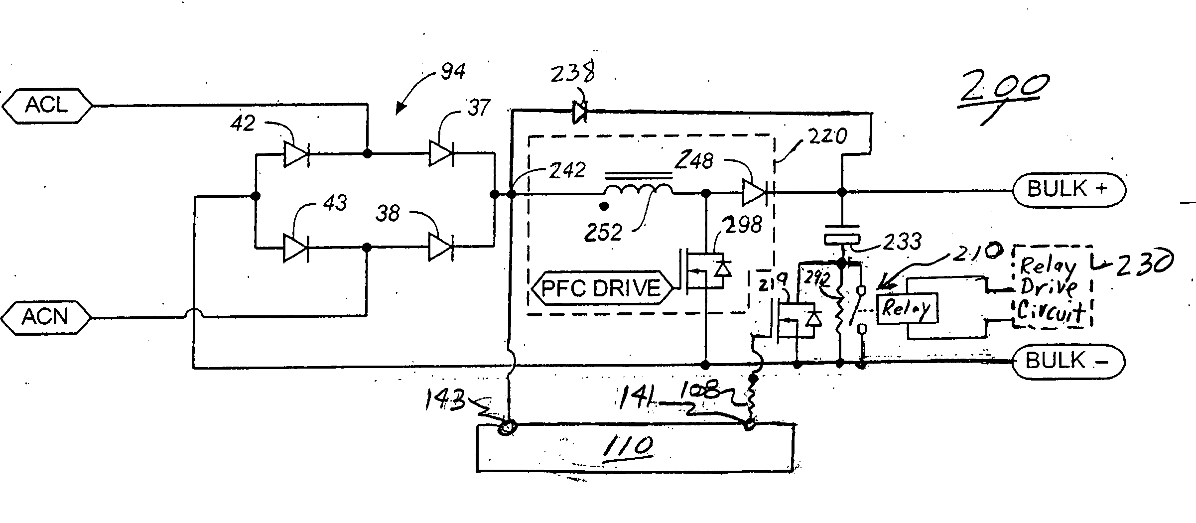
[0059]FIG. 7A shows a circuit diagram of a preferred embodiment of an AC-DC power converter 200 according to the present invention. Converter 200 is operatively connected between an AC input voltage (shown appearing across terminals ACL and ACN) from an AC voltage source (not shown) and an DC bulk output voltage appearing across terminals “Bulk+” and “Bulk-”. The DC bulk output voltage is typically applied to the inputs of a DC-DC converter (not shown) to provide further regulation and / or voltage conversion. The AC input voltage is coupled to a bridge rectifier 294. The bridge rectifier 294 comprises diodes 237, 238, 242, a...


PUM


Abstract

A circuit and corresponding method for controlling inrush current in an AC-DC power converter by providing a relay and a control circuit for limiting inrush current efficiently during cold startup, warm startup, and power line disturbance conditions. The relay is preferably connected in series with a bulk capacitor of the converter and in parallel with a limiting resistor and switch for shunting the resistor and switch so as to improve efficiency during operating conditions, at reduced size and cost. A preferred embodiment includes use of the circuit for AC-DC converters having active power factor correction.

Description

FIELD OF INVENTION [0001] The present invention relates to controlling inrush current in a power supply, and more particularly, to circuitry for controlling inrush current efficiently during cold startup, warm startup and power line disturbance conditions. BACKGROUND OF THE INVENTION [0002] The control of inrush current is especially important in N+1 redundant power systems. If excessive inrush current blows a fuse or trips the main circuit breaker on an AC distribution board, then the redundancy of the entire system is lost, even if the power supply is still functioning properly. The inrush current requirements of modern power supplies are very stringent, demanding efficient control of inrush current even during abnormal power line disturbances and for high current applications. [0003] To control inrush current, conventional methods may employ a relay, a negative temperature coefficient (NTC) thermistor, thyristor or similar switch, often in combination with a resistor or thermisto...

Claims


Application Information

Patent Timeline
Patent Type & Authority Applications(United States)
IPC IPC(8): H02H3/08
CPCH02M7/125H02H9/001
Inventor PHADKE, VIJAY GANGADHAR
Owner ASTEC INT LTD
Why Eureka
Try Eureka