
High NA system for multiple mode imaging

a high-na system and imaging mode technology, applied in the field of catadioptric optical systems, can solve the problems of difficult detection of changes in the height of features in most imaging modes, affecting the operation of the image processing system, and requiring several separate, very expensive machines for full inspection of an object, etc., to achieve the effect of facilitating simultaneous operation, facilitating maximum flexibility, and relaxing manufacturing tolerances

Inactive Publication Date: 2006-12-14
KLA CORP
View PDF14 Cites 7 Cited by
  • Summary
  • Abstract
  • Description
  • Claims
  • Application Information

AI Technical Summary

Benefits of technology

[0040] The catadioptric group includes a fused silica single near flat reflector and a dome-shaped reflector arranged in a catadioptric group. The near flat reflector can be a parallel fused silica plate having zero power, thereby making the catadioptric group easy to align. The focusing optics group includes eight lens elements in one embodiment. The focusing optics group corrects for high order spherical aberration and coma.
[0057] A further embodiment of the current design provides a relayed pupil for better access to the Fourier plane. Transferring the pupil to an external plane affords easy simultaneous operation of various imaging schemes.

Problems solved by technology

Full inspection of an object, such as a semiconductor wafer, requires several separate very expensive machines.
Most imaging modes have difficulty detecting changes in the height of features.
Collection angles are also limited to the range of angles within the NA of the objective.
This objective pupil feature seriously limits the types of illumination and Fourier filtering that are possible.
This high angle illumination is not possible without a higher NA objective.
This seriously limits the number of resolvable points in the image and the achievable inspection speed.
Another problem with this technique is small amounts of scattered and reflected light from lens elements in this system have the ability to produce noise at levels that compromise the sensitivity.
Introducing laser illumination from inside this type of objective can cause a significant amount of scattered and reflected light from the multiple lens surfaces.
The system must deal with scattered light from the lenses, illumination beam and the specular reflection from the wafer, which is a tremendous potential problem.
If the system uses a small spot for high sensitivity detection, the inspection speed tends to decrease dramatically.
If a larger spot size is used to increase inspection speed, the overall system sensitivity degrades.
This makes the combination of the double dark field mode and other imaging modes such as bright field and laser directional dark field difficult.
First, physical limitations tend to restrict the angle at which light beams may be applied to the object, i.e. at either extremely deep or extremely shallow angles.
This angular limitation tends to impede a full examination of the object.
Secondly, these systems only employ one dark field mode each, which again tends to limit the types of defects which may be detected.
Any attempt to combine different dark field imaging systems would be severely inhibited due to physical component placement restrictions and the inherent cost associated with multiple components.
The problem, however, is that no single mode provides these capabilities, nor is a combination of these modes physically realizable nor economically feasible.
Further, the use of multiple arrangements running over different machines negatively effects the scanning, processing, and evaluating time for each specimen.
While these systems may have a similar appearance to the present invention, they simply do not have the capability to integrate multiple inspection modes.
This limited NA and field size does not support high speed inspection with more than one dark field mode.
This limits its maximum pixel size and data collection speed.
This is a 0.9 NA system with very tight manufacturing tolerances, primarily due to the broad-band requirements of the design.
Calcium fluoride has excellent UV transmission properties but it is not necessarily a desirable glass because it is difficult to polish, not mechanically stable, and expensive.
Common problems with using several of these prior catadioptric optical systems for multiple imaging modes includes: these are complicated systems with tight manufacturing tolerances, they provide no illumination and imaging above 0.9 NA and a field of view less than 1 mm, pupil planes that are not easily accessible, and limited imaging modes and associated illumination schemes.

Method used


Image

  • High NA system for multiple mode imaging
  • High NA system for multiple mode imaging
  • High NA system for multiple mode imaging

Examples


Embodiment Construction

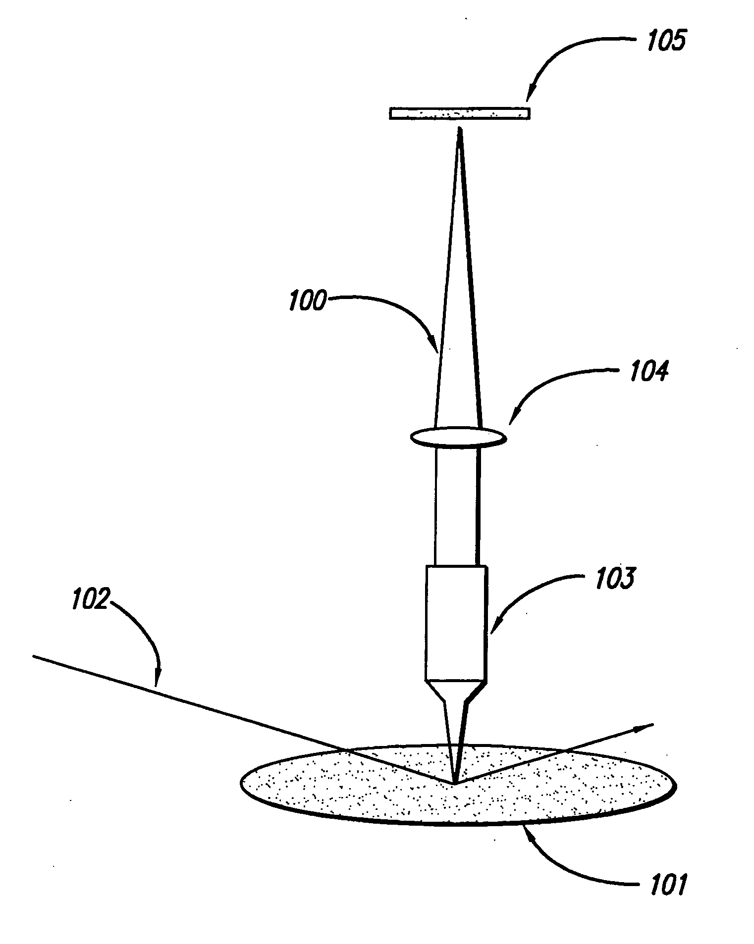
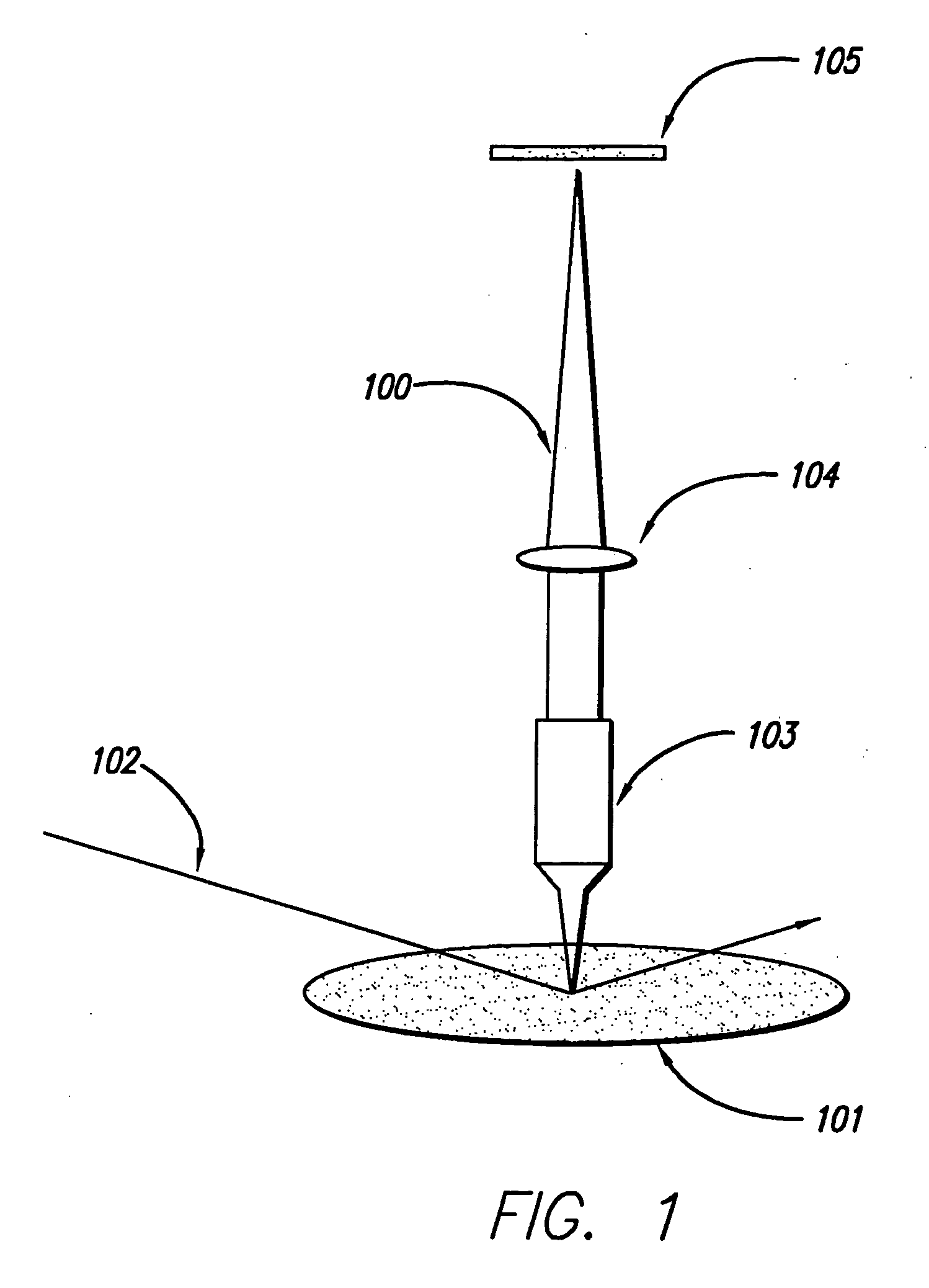
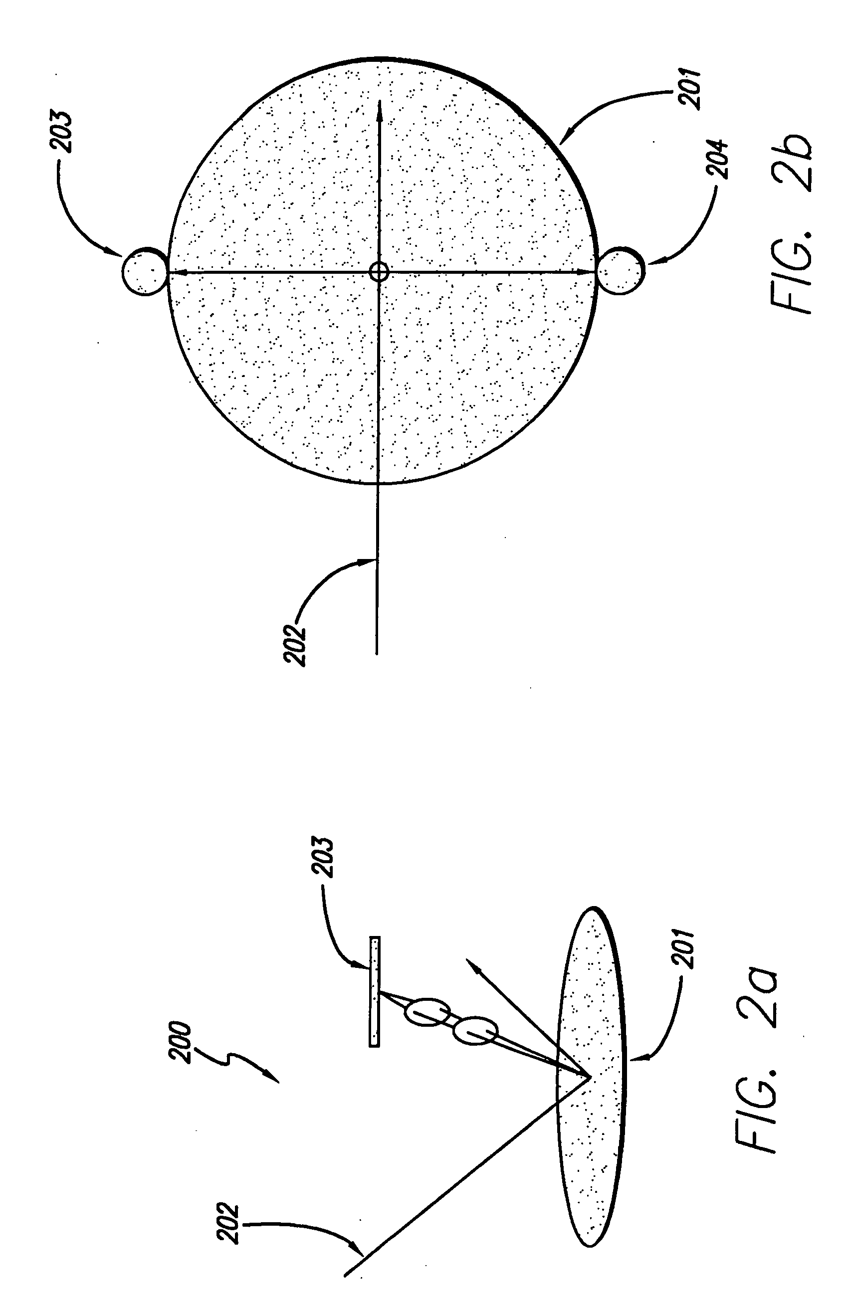
[0087] Referring now to FIG. 7, shown is a figure illustrating an apparatus that combines the functions of several imaging systems. This apparatus, based on a high NA catadioptric optical design, is a narrow band optical system having an NA greater than 0.90 and is highly corrected for low and high order monochromatic aberrations. The system of the present invention may have a numerical aperture of greater than 0.65. Preferably the numerical aperture is greater than 0.90. The field size preferably ranges from 0.5 to 2.0 mm.

[0088] This high NA catadioptric optical design has been optimized with emphasis on manufacturability and flexibility for a multiple mode optical inspection system. Previous catadioptric systems were primarily optimized for broad band performance. For this reason these prior systems had NAs limited to 0.90 and field sizes limited to 1 mm. Previous designs had a tendency to be highly complicated with tight manufacturing tolerances and required two glass materials,...


PUM

PropertyMeasurementUnit
angleaaaaaaaaaa
illumination anglesaaaaaaaaaa
collection anglesaaaaaaaaaa

Abstract

A system for multiple mode imaging is disclosed herein. The system is a catadioptric system preferably having an NA greater than 0.9, highly corrected for low and high order monochromatic aberrations. This system uses unique illumination entrances and can collect reflected, diffracted, and scattered light over a range of angles. The system includes a catadioptric group, focusing optics group, and tube lens group. The catadioptric group includes a focusing mirror and a refractive lens / mirror element. The focusing optics group is proximate to an intermediate image, and corrects for aberrations from the catadioptric group, especially high order spherical aberration and coma. The tube lens group forms the magnified image. Different tube lens groups can be used to obtain different magnifications, such as a varifocal tube lens group to continuously change magnifications from 20 to 200×. Multiple imaging modes are possible by varying the illumination geometry and apertures at the pupil plane. Imaging modes include bright-field, full sky, ring dark-field, inverted ring dark-field, directional dark-field, double dark-field, Manhattan geometry, confocal bright-field, confocal dark-field, conoscopic, etc. Illumination can enter the catadioptric optical system using an auxiliary beamsplitter or mirror, or through the catadioptric group at any angle from 0 to 85 degrees from vertical. Multiple beams at multiple angles may be used for illumination. The high NA catadioptric system can also have a relayed pupil plane, used to select different imaging modes, providing simultaneous operation of different imaging modes, Fourier filtering, and other pupil shaping operations.

Description

[0001] This application is a continuation in part of co-pending U.S. patent application Ser. No. 08 / 908,247, entitled “Ultra-Broadband UV Microscope Imaging System with Wide Range Zoom Capability,” filed on Aug. 7, 1997, which is a continuation in part of U.S. patent application Ser. No. 08 / 681,528, entitled “Broad Spectrum Ultraviolet Catadioptric Imaging System,” filed on Jul. 22, 1996, both of which are hereby incorporated by reference.BACKGROUND OF THE INVENTION [0002] 1. Field of the Invention [0003] The present invention relates generally to a method and apparatus for multiple mode imaging, and more particularly to catadioptric optical systems used for dark field imaging applications. [0004] 2. Description of the Related Art [0005] High precision optical instruments and imaging systems used in many different applications must operate effectively and efficiently. To accommodate optical functionality under varied conditions, precision lenses are often employed in different compl...

Claims


Application Information

Patent Timeline
Patent Type & Authority Applications(United States)
IPC IPC(8): G02B23/00G01N21/33G02B13/14G02B17/08G02B21/16G03C5/16G03F1/00G03F1/84G03F3/00G03F7/20H04N5/225
CPCG02B13/12G03F7/7065G02B17/08G02B17/0808G02B17/0812G02B17/0852G02B17/0856G02B17/0892G02B21/16G03F1/0092G03F1/84G03F7/70225G03F7/70275G03F7/70616G02B13/22
Inventor CHUANG, YUNG-HOSHAFER, DAVIDTSAI, BIN-MING B.ARMSTRONG, J. JOSEPH
Owner KLA CORP
Learn More