Process for producing conductive rubber roller, and roller for electrophotographic apparatus

a technology of conductive rubber and electrophotography, which is applied in the direction of filament/thread forming, textiles and paper, synthetic resin layered products, etc., can solve the problems of unsuitable for producing rollers in a large number, uniform cell foam obtained in the roller foam, and grinding, etc., to achieve uniform resistivity and hardness, small variation in resistivity, and stable hardness

Inactive Publication Date: 2006-12-14
CANON KK
View PDF4 Cites 28 Cited by
  • Summary
  • Abstract
  • Description
  • Claims
  • Application Information

AI Technical Summary

Benefits of technology

[0040] According to the conductive rubber roller production process of the fourth-object invention, the contact area between the rubber layer before vulcanization and foaming and the transporting mesh belt is optimized to bring about no foaming non-uniformity, and hence a conductive rubber roller can be provided which has uniform resistivity and hardness over the whole roller region. Besides, since no foaming non-uniformity may come about, grinding may be carried out in a minimum quantity, thus an economically and environmentally favorable production process is provided.
[0041] According to the conductive rubber roller production proc

Problems solved by technology

In these methods, e.g., in the method of carrying out vulcanization by means of a vulcanizer, the cells in the roller foam obtained are so non-uniform that grinding must be carried out in a large quantity in order to expose the desired cells to the surface.
Hence, it has been unsuitable for producing rollers in a large number.
Firstly, although the method making use of UHF vulcanization can be easily prepared and provides uniform cells, the tube formed may collapse when the rubber is softened, resulting in non-uniform aspect ratios of tube inner and outer diameters.
This non-uniformity of the tube has created the non-uniformity of hardness and electrical resistance in the peripheral direction.
However, this method requires a long and large apparatus and takes a long time to excessively irradiate the tube with microwaves, whereby the properties of the rubber materials, epichlorohydrin rubber and acrylonitrile-butadiene rubber, are changed, resulting the high volume resistivity of the rubber material.
Hence, the above method has been unsuitable for the conductive rubber rollers used in copying machines, printers and the like, and also there has been no presentation for any technical development directed to small-diameter rollers whose properties such as resistivity are required to delicately adjusted.
To this vulcanized rubber tube, a conductive core material coated at its preset position with a conductive adhesive is press-fitted, followed by heat treatment, where the rubber tube may partially come off because of non-uniformity of the adhesive, thereby resulting in non-uniform charging.
However, in conventional techniques, the dimensional stability of inner diameter is insufficient so that further improvement in precision has been sought for products.
Secondly, although the UHF vulcanization can be easily prepared and provides uniform cells, the rubber softens to come to have a larger area in contact with a conveyor and a roller when the rubber tube is heated in a furnace, thereby creating local non-uniformity in foaming.
Especially where the rubber softens greatly, the rubber tube deforms to change in its inner diameter, resulting in a poor yield of the rubber tube to bring about an economical problem.
Further, the foaming non-uniformity occurring in the rubber tube has been the cause of the non-uniformity of hardness and electrical resistance in the peripheral direction (see Japanese Patent Application Laid-open No. 2002-221859).
However, this has not remedied the foaming non-uniformity.
In all the ca

Method used


Image

  • Process for producing conductive rubber roller, and roller for electrophotographic apparatus
  • Process for producing conductive rubber roller, and roller for electrophotographic apparatus
  • Process for producing conductive rubber roller, and roller for electrophotographic apparatus

Examples


examples 5-1 to 5-5

&, COMPARATIVE EXAMPLES 5-1 TO 5-5

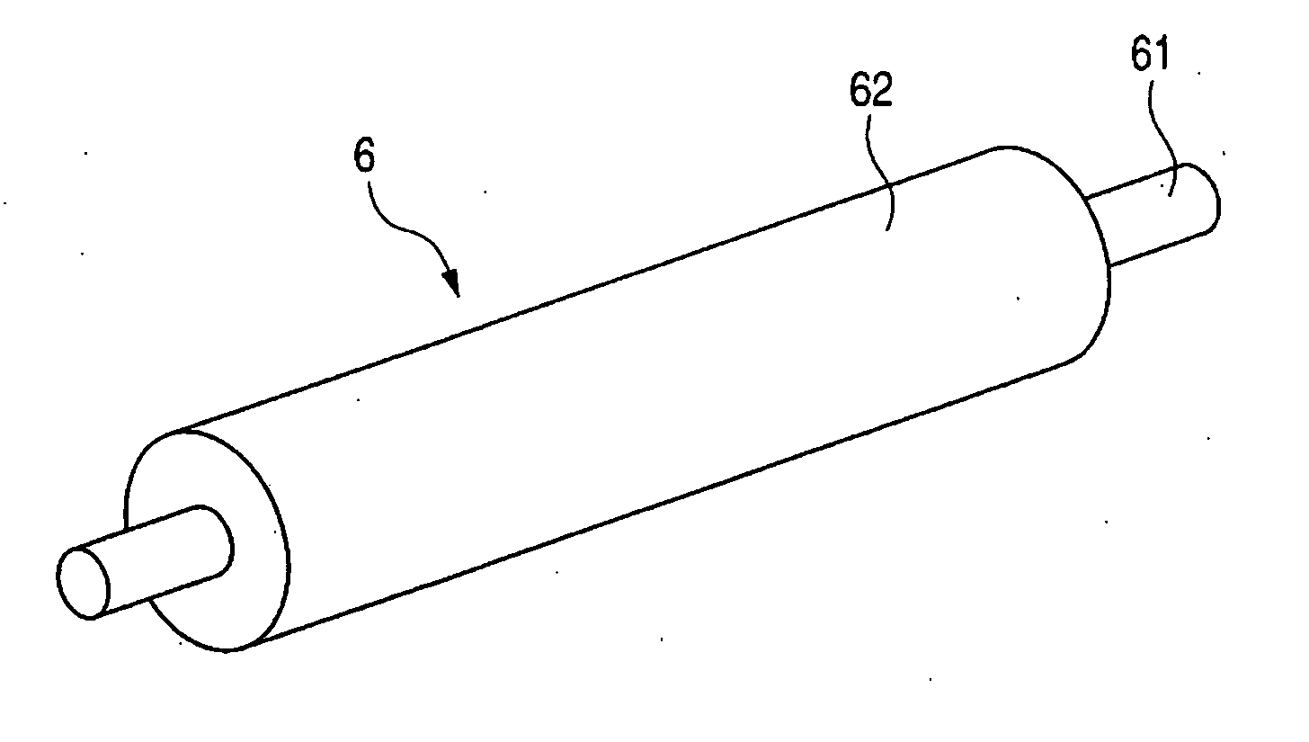
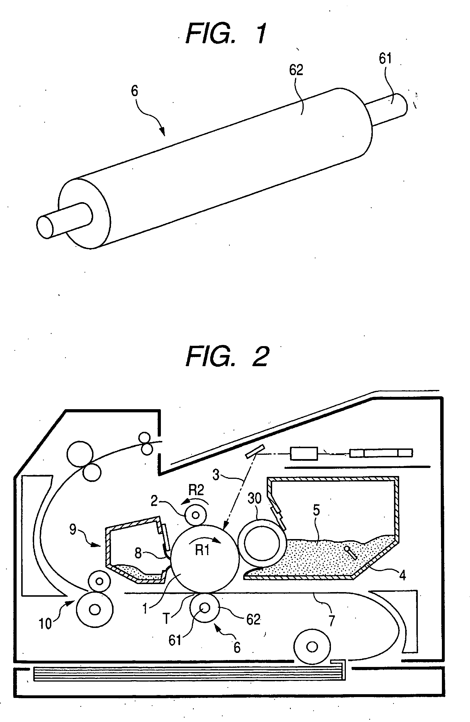
[0164] Conductive rubber rollers (FIG. 1) which demonstrate the present invention were produced in the following way.

[0165] 75 parts by mass of acrylonitrile-butadiene rubber (DN401, trade name, available from Nippon Zeon Co., Ltd.), 10 parts by mass of epichlorohydrin rubber (GECHRON 3106, trade name, available from Nippon Zeon Co., Ltd.), 15 parts by mass of ethylene oxide-propylene oxide-allyl glycidyl ether terpolymer (compositional proportion of propylene oxide: 1.30 mol %; compositional proportion of allyl glycidyl ether: 11.7 mol %; a trial product), 4 parts by mass of azodicarbonamide (VINYFOR AC, trade name, available from Eiwa Chemical Ind. Co., Ltd.), 1 part by mass of stearic acid (LUNAC S20, trade name, available from Kao Corporation), 5 parts by mass of zinc oxide (Zinc White JIS 1, trade name, available from Hakusui Chemical Industries, Ltd.) and 10 parts by mass of carbon (ASAHI 35, trade name, available from Asahi Carbon Co., Ltd.)...


PUM

PropertyMeasurementUnit
Temperatureaaaaaaaaaa

Abstract

This invention provides a process for producing a conductive rubber roller having small aspect ratios of inner and outer diameters, having a stable measure of its inner diameter, having uniform cell distribution and being free from non-uniformity of hardness and electrical resistance in the peripheral direction. The process has a step of continuously extruding a tube composed of a specific unvulcanized rubber composition from a rubber extruder in a microwave vulcanizing unit, and a step of foaming and vulcanizing the tube by using a microwave irradiator having a microwave irradiation zone 4 m or less in length while being transported at given speed. The foamed rubber tube has an inner diameter 20 to 35% smaller than the outer diameter of the conductive core material over the whole region in the lengthwise direction, and the conductive core material is press-fitted into the foamed rubber tube without using any adhesive.

Description

[0001] This application is a continuation of International Application No. PCT / JP2006 / 302912, filed Feb. 14, 2006, which claims the benefit of Japanese Patent Application No. 2005-036079 filed Feb. 14, 2005, Japanese Patent Application No. 2005-036080 filed Feb. 14, 2005, Japanese Patent Application No. 2005-047222 filed Feb. 23, 2005, Japanese Patent Application No. 2005-049003 filed Feb. 24, 2005, Japanese Patent Application No. 2005-053816 filed Feb. 28, 2005, and Japanese Patent Application No. 2006-027022 filed Feb. 3, 2006.BACKGROUND OF THE INVENTION [0002] 1. Field of the Invention [0003] This invention relates to a process for producing a conductive rubber roller used in image forming apparatus such as an electrophotographic copying apparatus, a printer and an electrostatic recording apparatus, and also to a roller for electrophotographic apparatus, such as a transfer roller, set in an image forming apparatus in which a tansferable image composed of a toner image is formed a...

Claims


Application Information

Patent Timeline
IPC IPC(8): G03G15/16B32B3/26B32B1/08B29D99/00
CPCB29C44/08B29C67/2245B29C2035/0855B29K2021/00B29K2105/04Y10T29/49544B29C35/10F16C13/00G03G15/14Y10T29/4956Y10T29/49563G03G15/1685B29C44/507Y10T428/249953Y10T428/31511Y10T428/31931C08J3/28C08J5/00C08L9/00
Inventor IMASAKA, HIROSHIFUKUZAWA, SATOSHIOKUDA, MITSURUUMEKI, ERIKA
Owner CANON KK
Why Eureka
Try Eureka