Fuel battery system

a fuel cell and battery technology, applied in the field of fuel cell systems, can solve the problems of low power generation efficiency, and achieve the effect of improving power generation efficiency and preventing a temperature gradient in fuel cells

Inactive Publication Date: 2006-12-21
TOYOTA JIDOSHA KK
View PDF5 Cites 15 Cited by
  • Summary
  • Abstract
  • Description
  • Claims
  • Application Information

AI Technical Summary

Benefits of technology

[0007] The object of the invention is thus to solve the problem of the prior art technique and to prevent a temperature gradient in fuel cells and thereby improve the power generation efficiency.
[0008] The invention is directed to a fuel cell system including fuel cells, a fuel gas supply module that supplies a fuel gas to anodes of the fuel cells, and an oxidizing gas supply module that supplies an oxidizing gas to cathodes of the fuel cells. The fuel gas contains hydrogen as well as a hydrocarbon compound. The fuel cells have a catalyst supported on their anode side to accelerate an endothermic reaction of the hydrocarbon compound. The endothermic reaction consumes heat produced in the power generation process in the fuel cells and accordingly cools down the fuel cells without circulation of a coolant. This effectively prevents a potential temperature gradient, which is often observed in the conventional cooling system with a coolant, and thus enhances the power generation efficiency. The technique of the invention may be combined with the conventional cooling system with a coolant. Such combination advantageously reduces the required size of the cooling system. The endothermic reaction in the fuel cells is preferably a reaction of producing hydrogen from a hydrocarbon compound. One typical example of such reactions is steam reforming reaction. The shift reaction of producing hydrogen from carbon monoxide and steam may also be initiated in the fuel cells.

Problems solved by technology

The variation of the cooling efficiency inside the fuel cells causes a temperature gradient in the fuel cells and may lower the power generation efficiency.
This problem is not characteristic of the fuel cells having the solid electrolyte membranes but is commonly found in various types of fuel cells.

Method used


Image

  • Fuel battery system
  • Fuel battery system
  • Fuel battery system

Examples


first embodiment

A. First Embodiment

A1. System Configuration

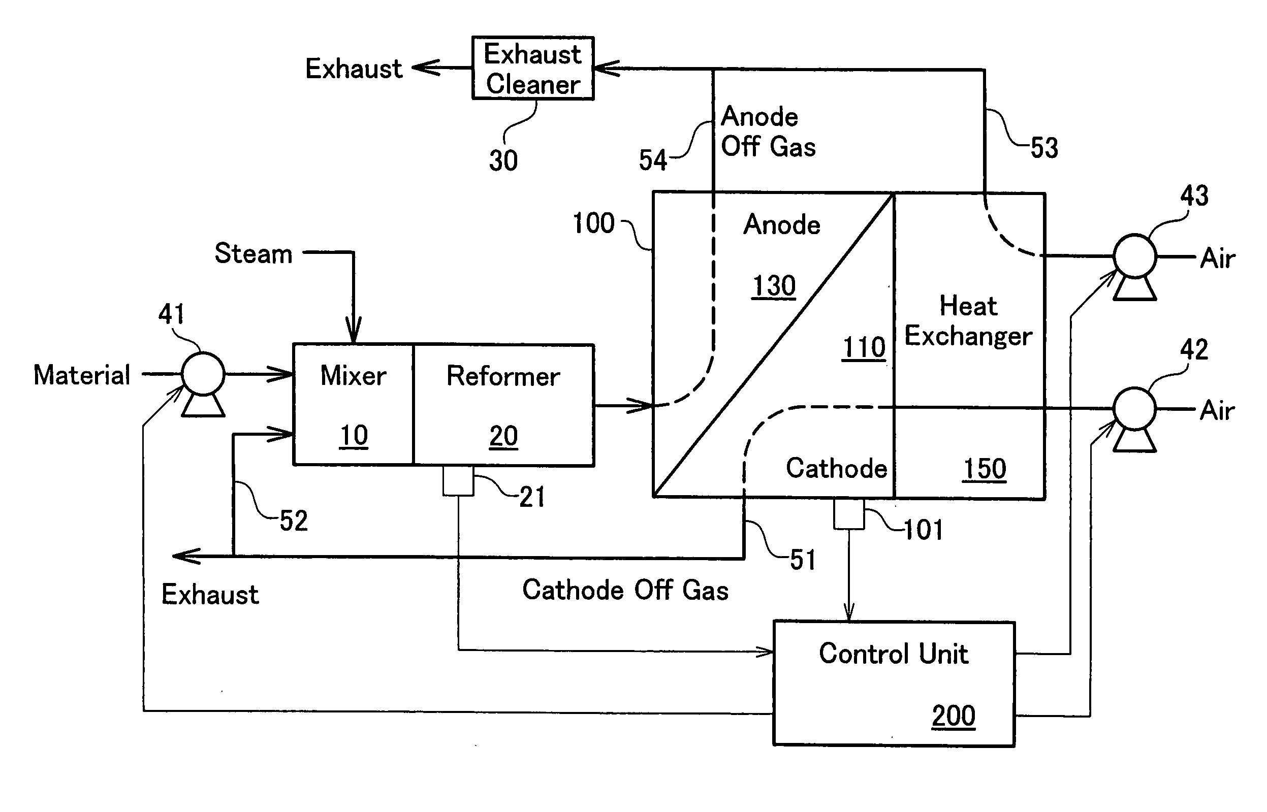
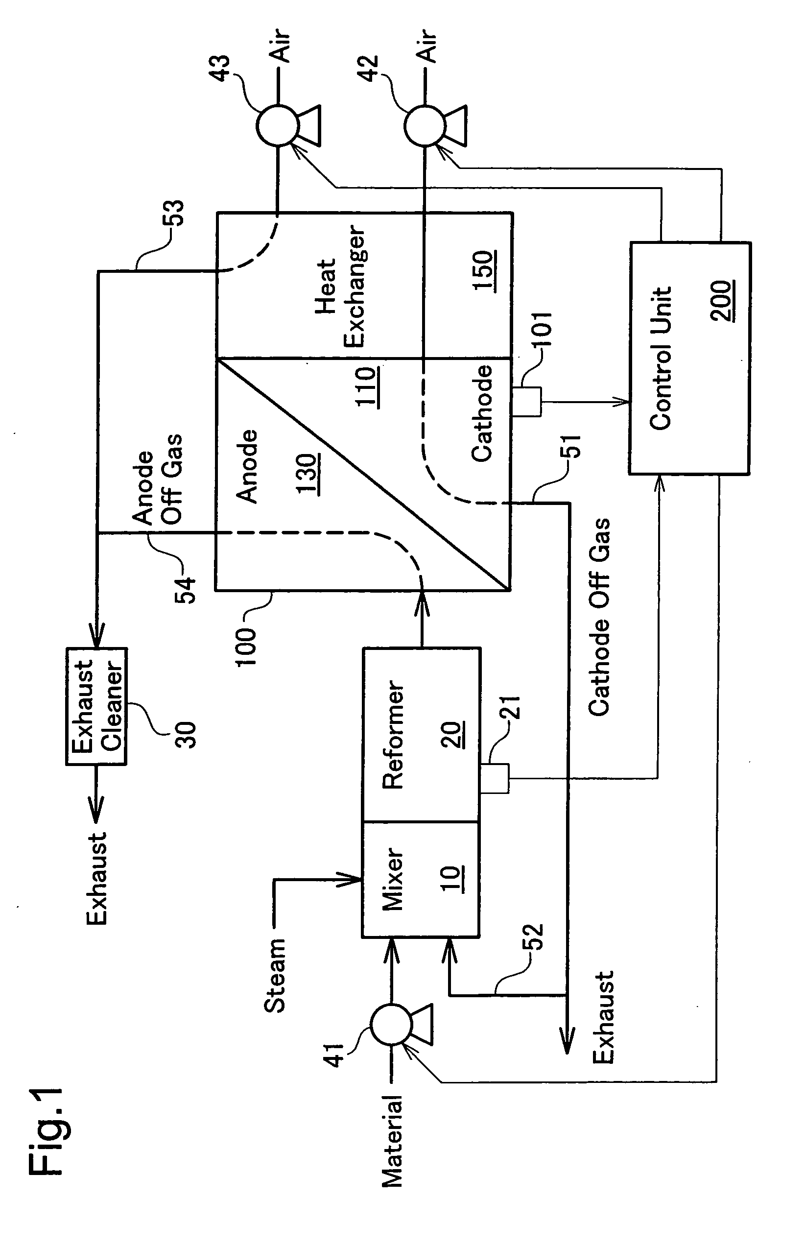
[0028]FIG. 1 schematically illustrates the configuration of a fuel cell system in a first embodiment. The fuel cell system of the first embodiment includes fuel cells 100 that generate electric power by an electrochemical reaction of hydrogen included in a supply of a fuel gas to anodes 130 with oxygen included in a supply of the air to cathodes 110. The fuel cells 100 have solid electrolyte membranes and are operated at a temperature of about 500° C. as described later in detail.

[0029] The intake air by a pump 42 flows through a heat exchanger 150 to cool the fuel cells 100 down and is then supplied to the cathodes 110. An exhaust gas from the cathodes 110 after the reaction (hereafter referred to as cathode off gas) is discharged through an exhaust conduit 51. Part of the cathode off gas is introduced via a branched pipe 52 into a mixer 10 to be used for a reforming reaction for generation of hydrogen, as described later.

[0030] The fu...

second embodiment

B. Second Embodiment

[0058]FIG. 6 schematically illustrates the configuration of another fuel cell system in a second embodiment. The fuel cell system of the second embodiment has a different structure related to production of the fuel gas, while including the fuel cells 100 of the same unit cell structure as that of the first embodiment.

[0059] In the system of the second embodiment, a combustor 25A is arranged besides a reformer 20A and receives a supply of the anode off gas through an exhaust conduit 54A and a supply of the air through air conduits 53A and 53B. The combustor 25A burns off the remaining hydrogen in the anode off gas to heat up the reformer 20A.

[0060] Like the first embodiment, the partial oxidation reaction proceeds in parallel with the steam reforming reaction in the reformer 20A. In the structure of the second embodiment, since the combustor 25A supplies some heat, the rate of the steam reforming reaction to the partial oxidation reaction is raised to be endothe...


PUM

PropertyMeasurementUnit
temperatureaaaaaaaaaa
thicknessaaaaaaaaaa

Abstract

Fuel cells 100 of the invention are operable at a temperature of about 500° C. The unit cell has a solid oxide electrolyte layer formed on a hydrogen separable metal layer. An anode has a catalyst supported thereon to accelerate a reforming reaction of methane. A fuel gas is produced by reforming a hydrocarbon-containing material in a reformer 20. Setting a lower reaction temperature enables production of the fuel gas containing both methane and hydrogen. In the fuel cells 100 receiving a supply of the fuel gas, the reforming reaction of methane contained in the fuel gas proceeds simultaneously with consumption of hydrogen contained in the fuel gas. This methane reforming reaction is endothermic to absorb heat produced in the process of power generation and thereby equalizes the operation temperature of the fuel cells 100.

Description

TECHNICAL FIELD [0001] The present invention relates to a fuel cell system and its control method. BACKGROUND ART [0002] Fuel cells generating electric power by an electrochemical reaction of hydrogen with the air have recently drawn attention as the novel energy source. Fuel cells having solid electrolyte membranes include low-temperature-operation-type fuel cells, such as polymer electrolyte fuel cells, and high-temperature-operation-type fuel cells, such as solid oxide fuel cells. [0003] The polymer electrolyte fuel cell has a solid polymer film, for example, a Nafion (registered trademark) film applied to an electrolyte membrane interposed between electrodes. A decrease in water content of this electrolyte membrane lowers the ion conductivity and increases the film resistance. Control of the film resistance in a practical range requires operation of these fuel cells in a relatively low temperature range that prevents extreme evaporation of the water content. The polymer electrol...

Claims


Application Information

Patent Timeline
Patent Type & Authority Applications(United States)
IPC IPC(8): H01M8/06H01M8/04H01M4/90H01M8/10H01M8/12
CPCC01B3/382Y02E60/525C01B2203/0244C01B2203/066C01B2203/067C01B2203/1047C01B2203/1058C01B2203/1223C01B2203/1241C01B2203/1276C01B2203/142C01B2203/143C01B2203/1619C01B2203/169H01M4/92H01M4/94H01M8/04007H01M8/04014H01M8/04097H01M8/04365H01M8/04373H01M8/04753H01M8/04776H01M8/0618H01M8/0637H01M8/1016H01M8/1023H01M8/1039H01M8/124H01M8/1246H01M2008/1095H01M2008/1293H01M2300/0068H01M2300/0082Y02E60/521C01B3/384Y02E60/50Y02P70/50
Inventor AOYAMA, SATOSHIIGUCHI, SATOSHINUMATA, KOICHIIIJIMA, MASAHIKOITO, NAOKI
Owner TOYOTA JIDOSHA KK
Why Eureka
Try Eureka