

Carrier, developer, image forming apparatus and process cartridge
a technology of carrier and developer, applied in the direction of electrographic process apparatus, instruments, developers, etc., can solve the problems of carrier adhesion not always being sufficiently prevented, the desorption force is sometimes higher than the binding force, and the inability to prevent carrier adhesion
- Summary
- Abstract
- Description
- Claims
- Application Information
AI Technical Summary
Benefits of technology
Problems solved by technology
Method used
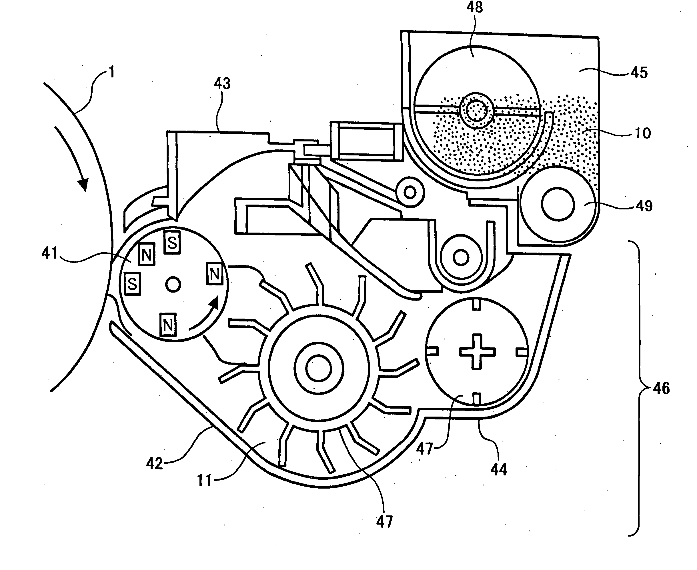
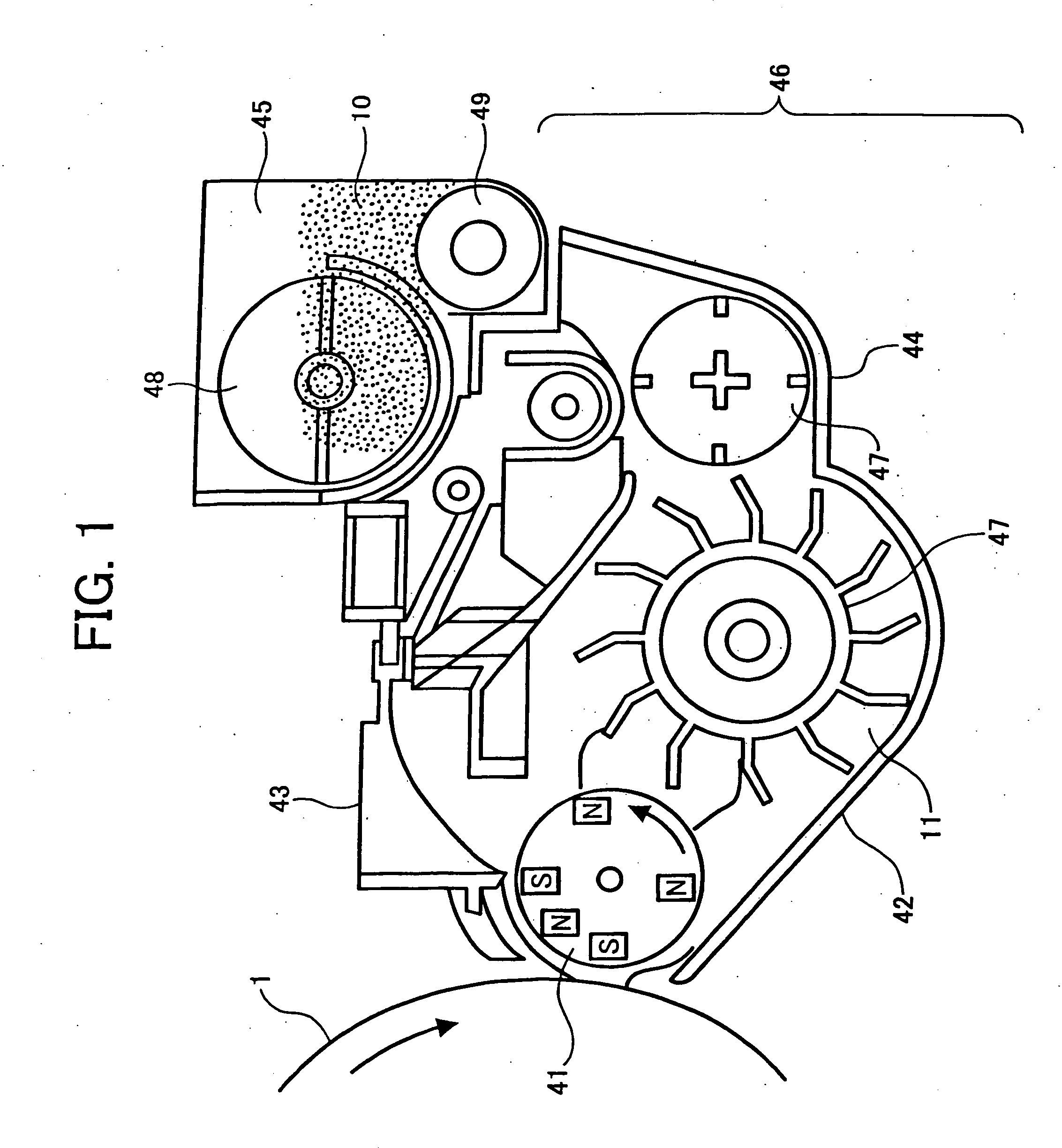
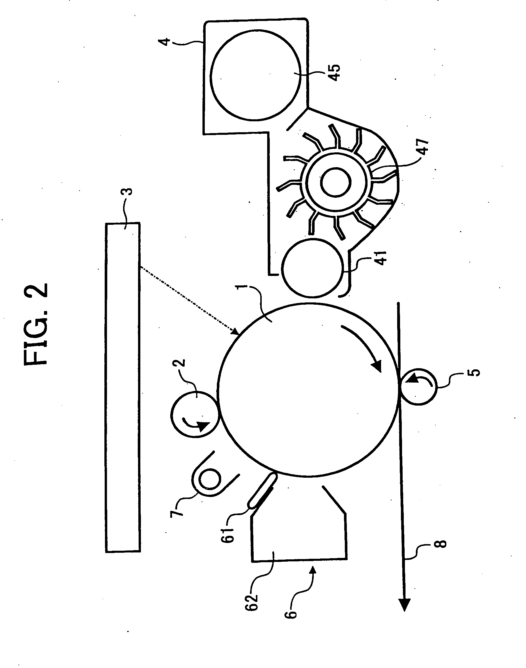
Image

Examples
example 1
[0186] Manganese oxide and iron oxide were mixed at a molar ratio (Mn / Fe) of 35 / 65. After the mixture was pulverized and dispersed by a ball mill in water using a wet pulverizing and dispersing method for 48 hrs, the mixture was dried and pre-fired at 900° C. for 1 hr in a weak reducing atmosphere.
[0187] The wet pulverization was performed by filling zirconia balls, having a diameter of 10 mm, in a ball mill pot at 30% by volume of the ball mill pot capacity and an oxide slurry having a solid content of 25% by 20% by volume of the slurry.
[0188] Afler crushed, the pre-fired mixture was pulverized and dispersed again by a ball mill in water by a wet pulverizing and dispersing method for 24 hrs to prepare a slurry of manganese and iron complex oxide.
[0189] Polyvinylalcohol and a dispersant were added to the slurry as a binder, and the slurry was granulated and dried by a spray drier, and then classified by a supersonic vibration sieve to prepare granulated particles.
[0190] The gran...
example 2
[0214] The procedures for preparation and evaluation of the two-component developer in Example 1 were repeated except for pulverizing and dispersing the manganese oxide and iron oxide by a ball mill for 24 hrs instead of 48 hrs before pre-firing to prepare a core material (2) and a carrier (C2).
[0215] The evaluation results are shown in Tables 1-1, 1-2 and 1-3.
example 3
[0216] The procedures for preparation and evaluation of the two-component developer in Example 1 were repeated except for pulverizing and dispersing the manganese oxide and iron oxide by a ball mill for 120 hrs instead of 48 hrs before pre-firing and pulverizing and dispersing the mixture thereof by a ball mill for 48 hrs instead of 24 hrs after pre-firing to prepare a core material (3) and a carrier (C3).
[0217] The evaluation results are shown in Tables 1-1, 1-2 and 1-3.
PUM
| Property | Measurement | Unit |
|---|---|---|
| magnetic flux density | aaaaa | aaaaa |
| magnetization | aaaaa | aaaaa |
| particle diameter | aaaaa | aaaaa |
Abstract
Description
Claims
Application Information