Honeycomb structure
a honeycomb and structure technology, applied in the field of honeycomb structure, can solve the problems of increased thickness of alumina layer, increased probability of contact, and high pressure loss, and achieve the effect of increasing strength against thermal shock and high dispersion of catalyst components
- Summary
- Abstract
- Description
- Claims
- Application Information
AI Technical Summary
Benefits of technology
Problems solved by technology
Method used
Image
Examples
example 1
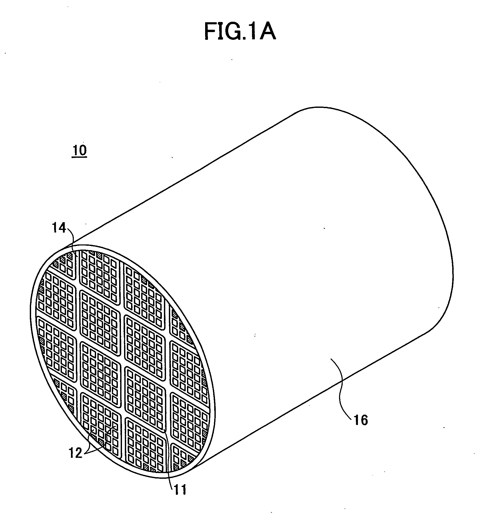
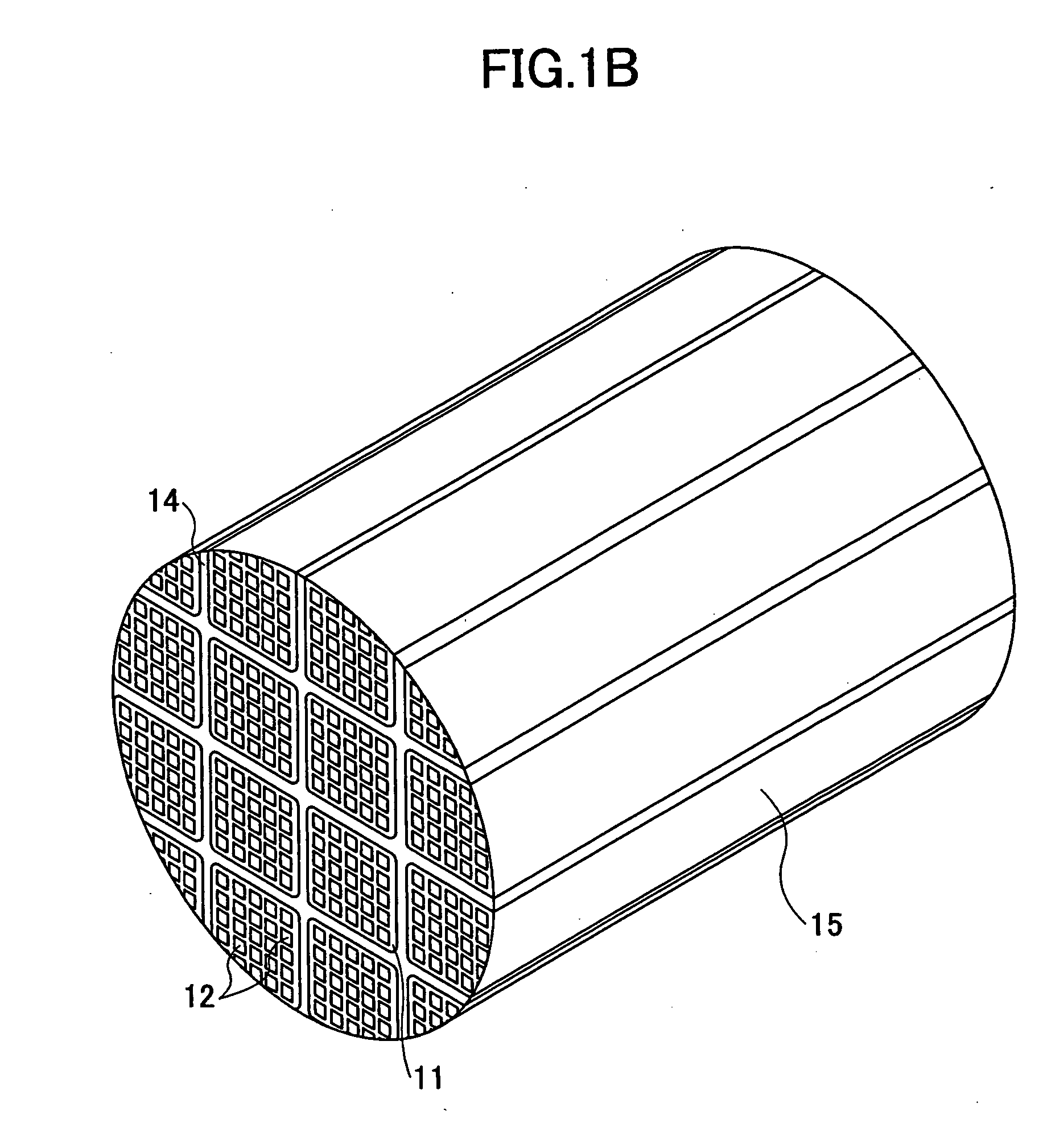
[0061] First, 40 wt % of γ-alumina particles (2 μm in average particle size), 10 wt % of silica-alumina fibers (10 μm in average fiber diameter, 100 μm in average fiber length, and of an aspect ratio of 10), and 50 wt % of silica sol (of a solid concentration of 30 wt %) were mixed. Six parts by weight of methylcellulose as an organic binder was added, together with small amounts of a plasticizer and lubricant, to 100 parts by weight of the obtained mixture. The mixture was further mixed and kneaded, so that a mixture composition was obtained. Next, the mixture composition was subjected to extrusion molding by an extruder, so that crude molded bodies were obtained.
[0062] The extrusion molding was performed using such a mold as to form a rounded-surface shape of a radius of curvature R of 1.5 mm on each corner 18 of the honeycomb units 11.
[0063] The crude molded bodies were sufficiently dried using a microwave drier and a hot air drier, and were degreased, being heated at 400° C. f...
examples a through t
[0071] In Examples A through J, the honeycomb structures 10 were made in the same manner as in Example 1 except that extrusion molding was performed with different molds so that the rounded-surface shapes of the corners 18 of the honeycomb units 11 had predetermined radii of curvature R, thereby varying the radius of curvature R from 0 to 3.0 mm. In Examples K through T, the honeycomb structures 10 were made in the same manner as in Example 1 except that extrusion molding was performed with different molds so that the corners 18 of the honeycomb units 11 had predetermined chamfered-surface shapes, thereby changing the chamfered-surface shapes of the corners 18 of the honeycomb units 11 from 0 to 3.0 mm. In Examples J and T, the coating material layer 16 was not provided on the external cylindrical surface of the honeycomb structure 10. Table 4 shows the radius of curvature R or the chamfered-surface shape of the corners 18 of the honeycomb units 11 of each example in combination-wit...
examples 2 through 7
[0072] The honeycomb structures 10 were made in the same manner as in Example 1 except that the honeycomb units 11 were made into respective shapes shown in Table 1. The shapes of the joint bodies of Examples 2, 3, and 4 are shown in FIGS. 4B, 4C, and 4D, respectively, and the shapes of the joint bodies of Examples 5, 6, and 7 are shown in FIGS. 5A, 5B, and 5C, respectively. In Example 7, the honeycomb structure 10 was monolithically formed, and accordingly, the joining process and the cutting process were not performed.
PUM
| Property | Measurement | Unit |
|---|---|---|
| area | aaaaa | aaaaa |
| size | aaaaa | aaaaa |
| thickness | aaaaa | aaaaa |
Abstract
Description
Claims
Application Information
 - R&D
- Intellectual Property
- Life Sciences
- Materials
- Tech Scout
- Unparalleled Data Quality
- Higher Quality Content
- 60% Fewer Hallucinations
Browse by: Latest US Patents, China's latest patents, Technical Efficacy Thesaurus, Application Domain, Technology Topic, Popular Technical Reports.
© 2025 PatSnap. All rights reserved.Legal|Privacy policy|Modern Slavery Act Transparency Statement|Sitemap|About US| Contact US: help@patsnap.com


