Energy device

a technology of energy devices and energy density, applied in the direction of non-aqueous electrolyte cells, cell components, sustainable manufacturing/processing, etc., can solve the problems of poor charge/discharge characteristics of conventional secondary batteries at large currents, and low energy density of electric double layer capacitors. , to achieve the effect of excellent input/output characteristics

Inactive Publication Date: 2007-01-04
HITACHI LTD
View PDF2 Cites 16 Cited by
  • Summary
  • Abstract
  • Description
  • Claims
  • Application Information

AI Technical Summary

Benefits of technology

[0008] It is therefore an object of the invention to provide a novel energy device that can overcome the disadvantages of the prior art and that has excellent input / output characteristics at low temperatures.
[0010] The novel energy device has excellent input / output characteristics at low temperature.

Problems solved by technology

The conventional secondary batteries, however, have poor charge / discharge characteristics at large currents, and particularly the input / output characteristics drop significantly at low temperature environments.
Furthermore, the electric double layer capacitor has a low energy density problem.

Method used


Image

  • Energy device
  • Energy device
  • Energy device

Examples


example 1

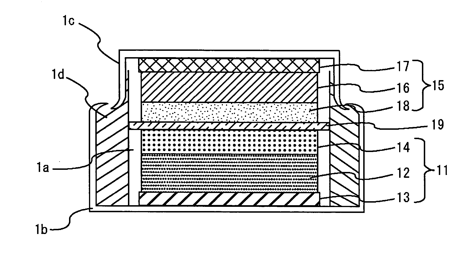
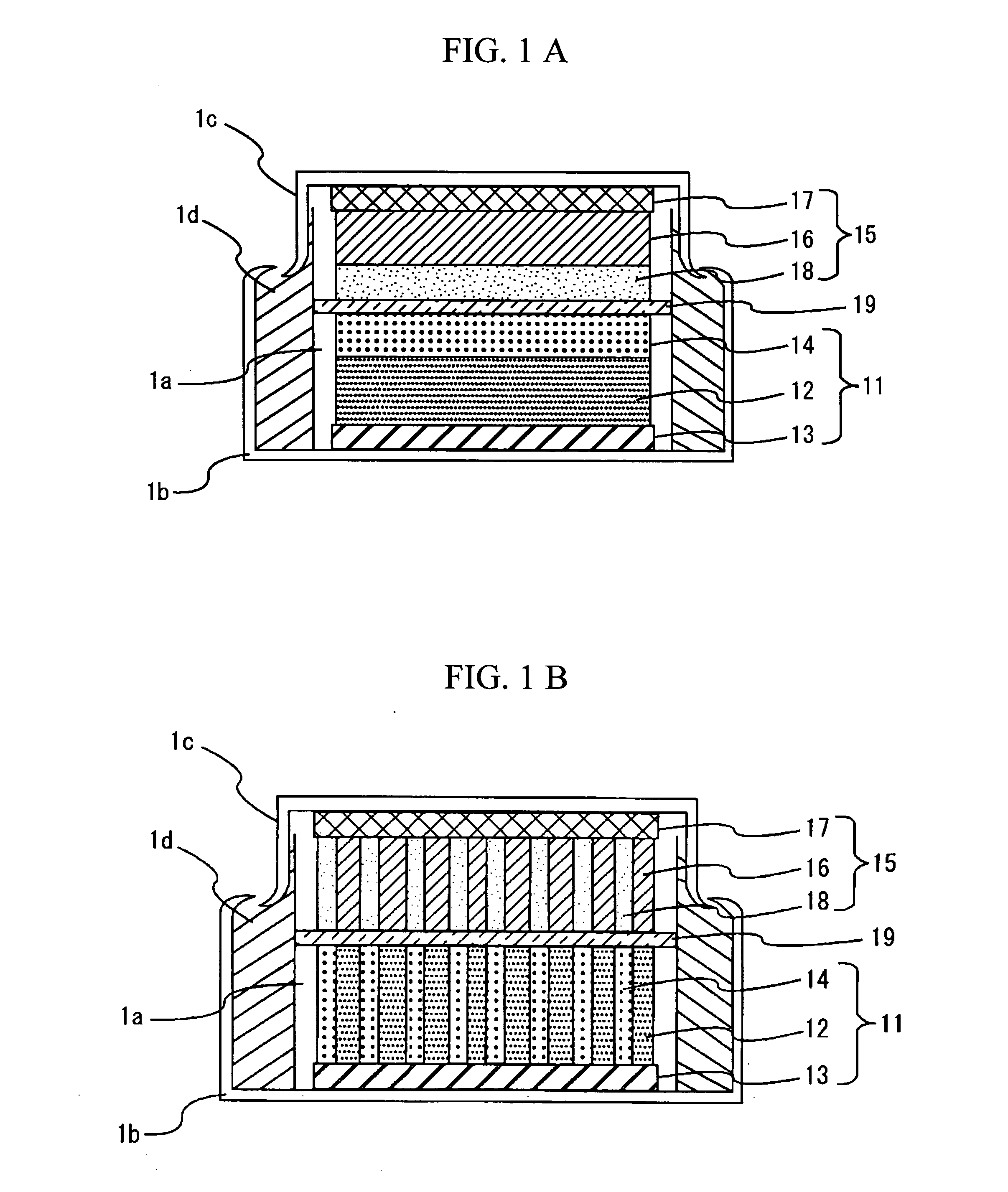
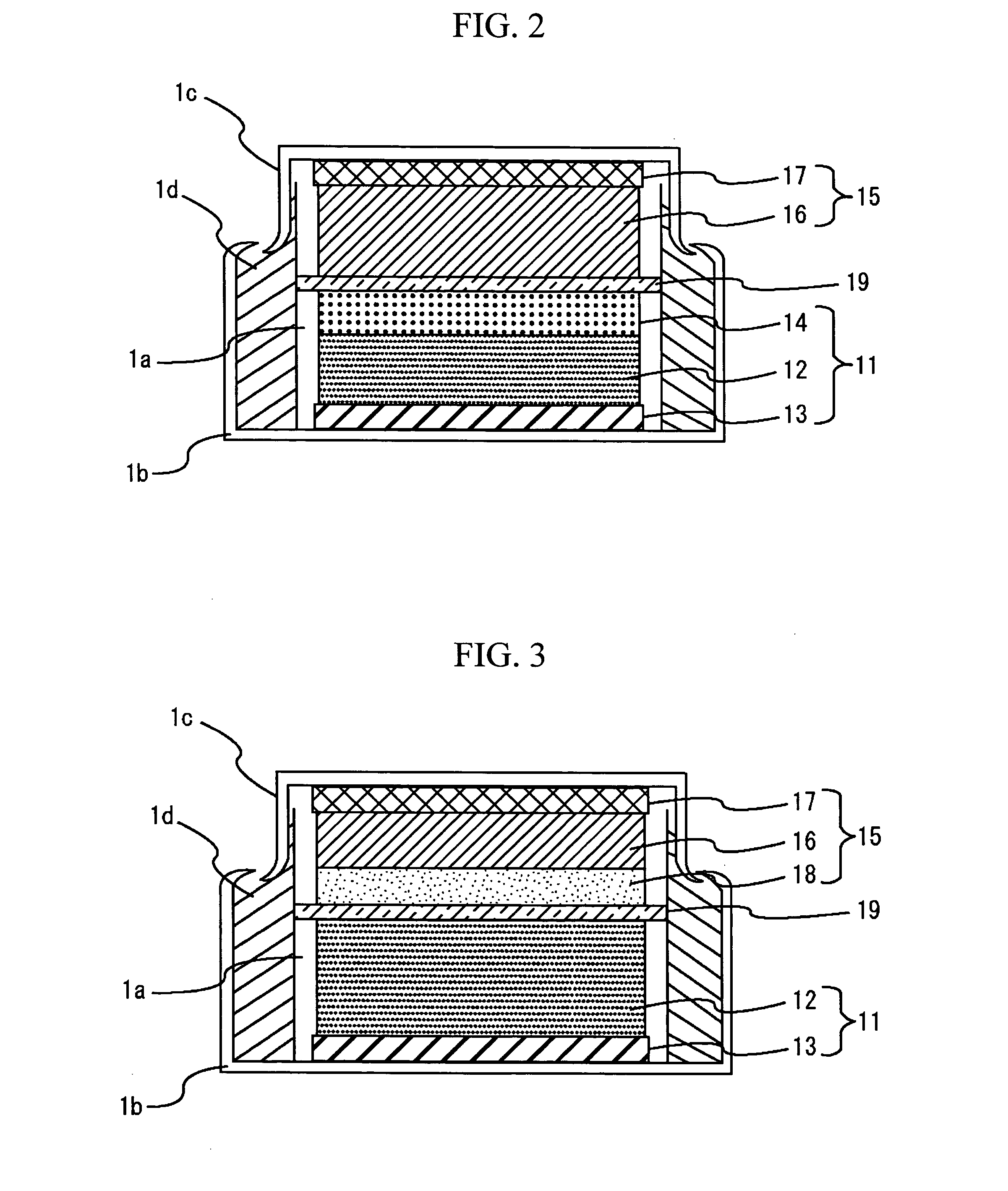
[0058] A coin type energy device with the configuration of FIG. 2 was made. The positive-electrode faradic reaction layer 12 was prepared as follows. The positive electrode active material was formed of Li1.05Mn1.95O4 with a mean particle size of 10 μm. The conductant agent was formed of a mixture with a weight ratio of 4:1 of graphite carbon with a mean particle size of 3 μm and specific surface area of 13 m2 / g, and carbon black with a mean particle size of 0.04 μm and specific surface area of 40 m2 / g. Using a binder made by dissolving 8 wt. % of polyvinylidene fluoride in N-methylpyrrolidone in advance, the positive electrode active material, conductant agent, and polyvinylidene fluoride were mixed to the weight ratio of 85:10:5, and the mixture was sufficiently kneaded, thereby obtaining a positive-electrode slurry. The positive-electrode slurry was applied to one side of positive-electrode collector 13 composed of an aluminum foil with a thickness of 20 μm and dried. The positiv...

example 2

[0060] An energy device was prepared in the same manner as in Example 1 except that the weight ratio of the positive electrode active material, conductant agent, polyvinylidene fluoride, and activated charcoal to the total weight of the positive-electrode faraday 12 and the positive-electrode non-faradic reaction layer 14 was 74:10:6:10 and the weight of the activated charcoal was 10 wt. %.

example 3

[0073] A coin type energy device with a configuration shown in FIG. 7 was made. For a positive-electrode faradic reaction layer 12, the positive-electrode slurry of Comparative Example 1 was applied to one side of a positive-electrode collector 13 consisting of an aluminum foil with a width of 1 mm and a thickness of 20 μm, leaving uncoated regions at 1 mm intervals, and the thus applied layer was then dried. Activated charcoal with a specific surface area of 2000 m2 / g and carbon black with a mean particle size of 0.04 μm and a specific surface area of 40 m2 / g were mixed to a weight ratio of 8:1. Using a binder consisting of a solution prepared by dissolving 8 wt. % of polyvinylidene fluoride in N-methylpyrrolidone in advance, the activated charcoal, carbon black, and polyvinylidene fluoride were mixed to a weight ratio of 80:10:10 and sufficiently kneaded, thereby preparing a slurry. The slurry was applied to the uncoated regions on the positive-electrode collector 13, thereby form...


PUM

PropertyMeasurementUnit
temperaturesaaaaaaaaaa
diameteraaaaaaaaaa

Abstract

An energy device with high input / output characteristics and superior characteristics particularly at low temperature. The energy device stores and releases electric energy by means of a faradaic reaction mechanism based mainly on the alteration of the oxidation state of an active material whereby charges move into the active material, and a non-faradaic reaction based mainly on the physical adsorption and separation of ions on the surface of an active material for storing or releasing charges. The output characteristics at low temperature are improved by employing at least two kinds of faradaic reaction mechanism, namely, one with low reaction rate and the other with high reaction rate, which is mainly based on the alteration of the oxide state of an active material for the transfer of charges into the active material via an electrode interface.

Description

BACKGROUND OF THE INVENTION [0001] 1. Field of the Invention [0002] The present invention relates to an energy device for storing and releasing electric energy. [0003] 2. Background Art [0004] In recent years, power supplies for electric vehicles, hybrid vehicles, or electric tools are required to have higher input and output capabilities. The are also required to be adapted for quicker charge and discharge operations and to have greater capacities. Particularly, power supplies are called for that have smaller temperature dependency and that can maintain their input and output characteristics at low temperatures, such as at −20° C. or −30° C. [0005] Such demands have so far been dealt with by performance improvements on the secondary batteries with faradaic reaction mechanism, such as lithium secondary batteries, nickel metal hydride batteries, nickel cadmium batteries, and lead-acid batteries. Another response has been to employ, in combination with any of the aforementioned second...

Claims


Application Information

Patent Timeline
Patent Type & Authority Applications(United States)
IPC IPC(8): H01M10/40H01M4/58H01G9/035H01M4/02H01M4/505H01M4/525H01M4/583H01M10/05H01M10/052H01M10/0525H01M10/0565H01M10/0568H01M10/0569
CPCH01G9/035Y02E60/13H01G11/02H01G11/06H01G11/56H01G11/62H01M4/131H01M4/133H01M4/134H01M4/136H01M4/366H01M4/505H01M4/525H01M4/587H01M4/602H01M10/052H01M10/0525H01M10/0565H01M10/0568H01M10/0569H01M2300/0025H01M2300/0085H01M2300/0091Y02E60/122Y02T10/7011Y02T10/7022H01G9/22Y02E60/10Y02T10/70Y02P70/50
Inventor KUMASHIRO, YOSHIAKIARAI, JUICHIKOBAYASHI, MITURU
Owner HITACHI LTD
Why Eureka
Try Eureka