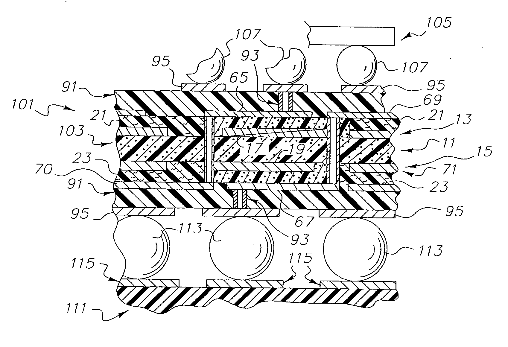
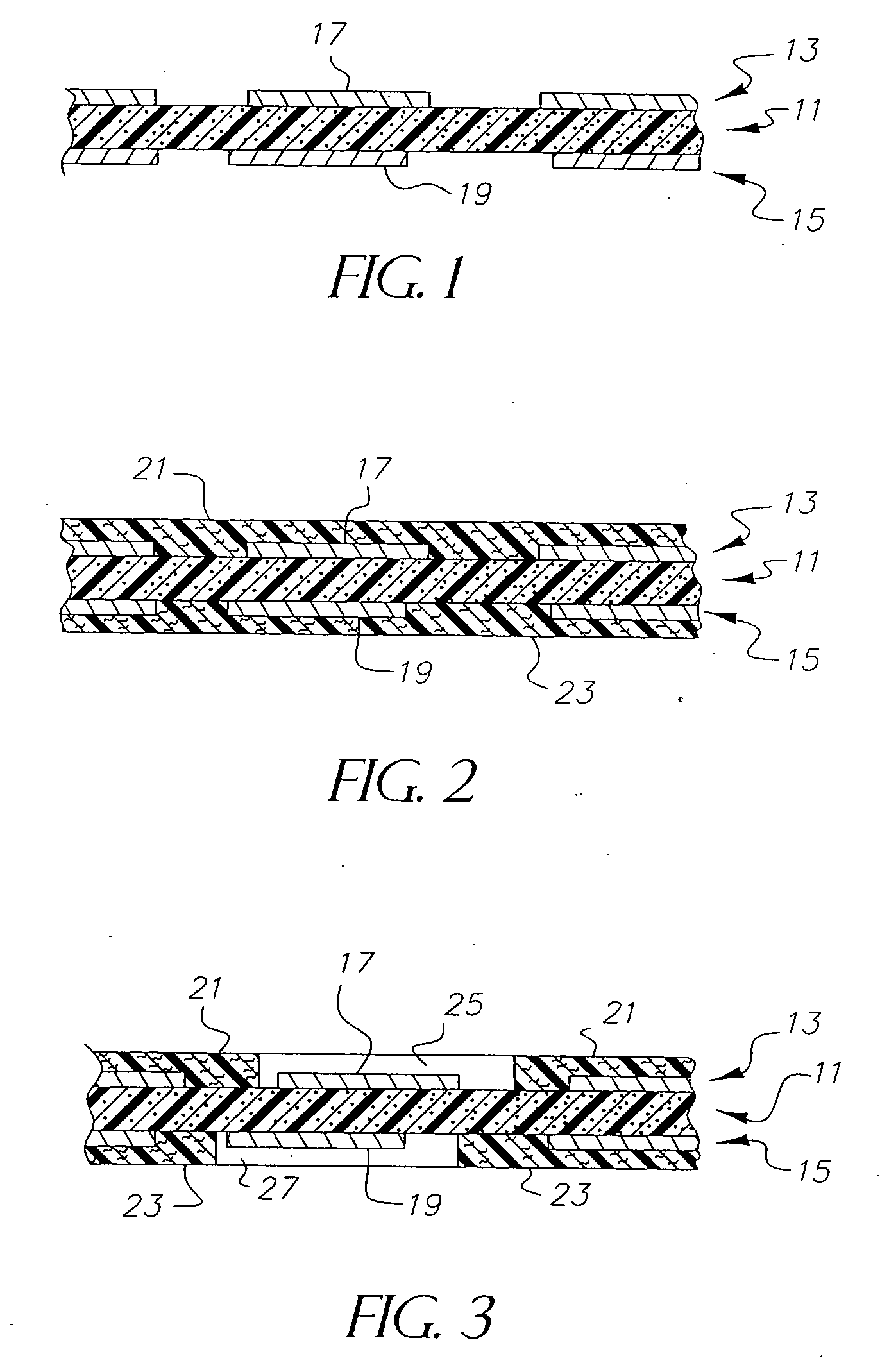
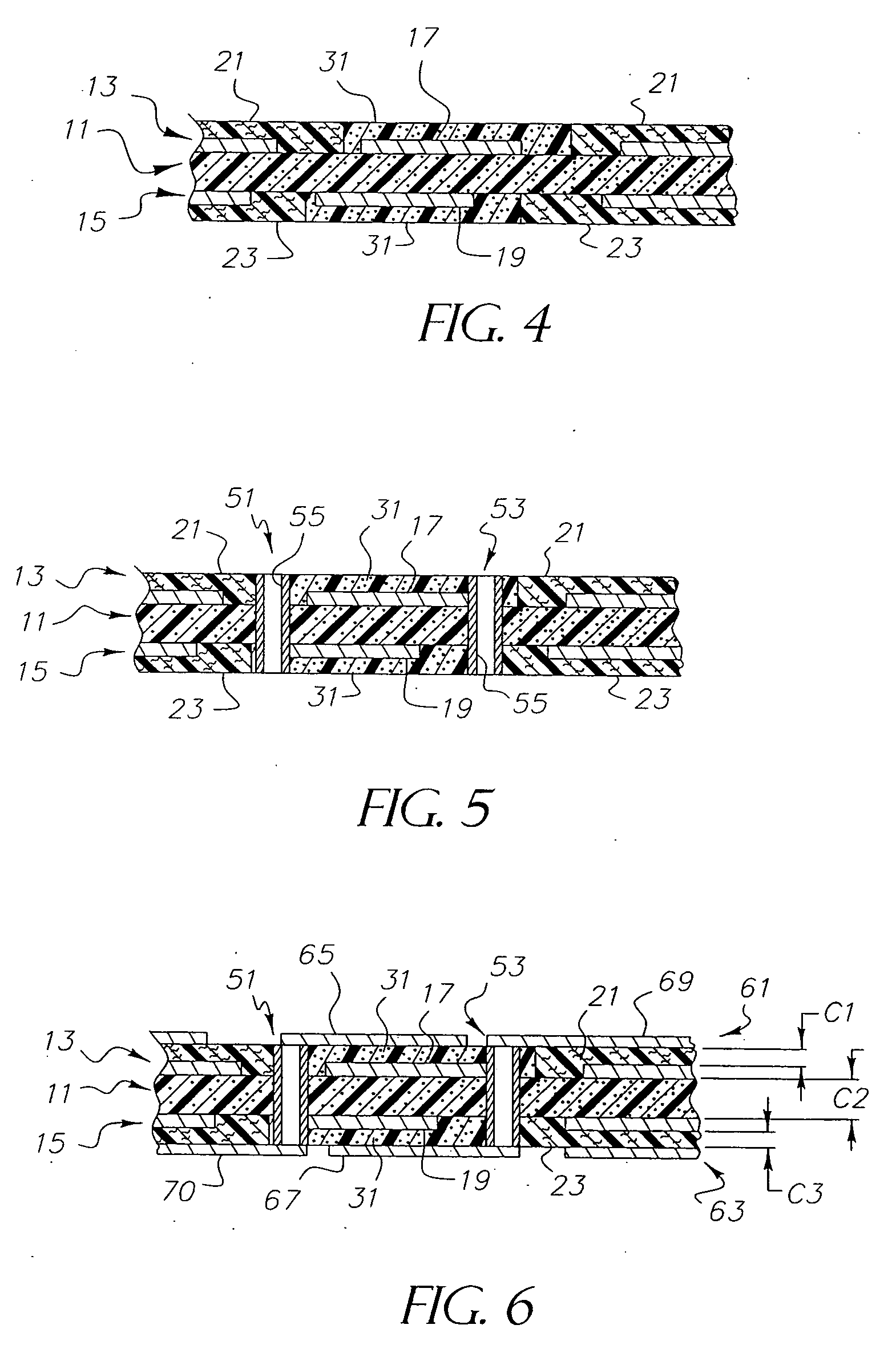
Method of making a capacitive substrate using photoimageable dielectric for use as part of a larger circuitized substrate, method of making said circuitized substrate and method of making an information handling system including said circuitized substrate

Inactive Publication Date: 2007-01-11
I3 ELECTRONICS
View PDF23 Cites 22 Cited by
  • Summary
  • Abstract
  • Description
  • Claims
  • Application Information

AI Technical Summary

Benefits of technology

[0037] It is, therefore, a primary object of the present invention to enhance the circuitized substrate art by providing a method

Problems solved by technology

The discrete passive devices occupy a high percentage of the surface area of the completed substrate, which is undesirable from a future design aspect because of the increased need and demand for miniaturization in today's substrates and products containing same art.
Some of the patents listed below, particularly U.S. Pat. No. 5,162,977, mention use of various materials for providing desired capacitance levels under this formula, and many mention or suggest problems associated with the methods and resulting materials used to do so.
Use of pre-fired and ground ceramic nano-powders in the dielectric layer poses obstacles for the formation of thru-holes (conductive holes permitting electronic communication between conductive layers of a PCB), however.
The distribution within the dielectric layer of particles of different size often presents major obstacles to thru-hole formation where the thru-holes are of extremely small diameter, also referred to in the industry as micro-vias due to the presence of the larger particles.
Another problem associated with pre-fired ceramic nano-powders is the ability for the dielectric layer to withstand substantial voltage without breakdown occurring across the layer.
This is even further undesirable because, as indicated by the equation cited above, greater planar capacitance may also be achieved by reducing the thickness of the dielectric layer.
That is, the re

Method used


Image

  • Method of making a capacitive substrate using photoimageable dielectric for use as part of a larger circuitized substrate, method of making said circuitized substrate and method of making an information handling system including said circuitized substrate
  • Method of making a capacitive substrate using photoimageable dielectric for use as part of a larger circuitized substrate, method of making said circuitized substrate and method of making an information handling system including said circuitized substrate
  • Method of making a capacitive substrate using photoimageable dielectric for use as part of a larger circuitized substrate, method of making said circuitized substrate and method of making an information handling system including said circuitized substrate

Examples


Example

EXAMPLE FOUR

[0079] Fifty gm of “ERL-4211” cycloaliphatic epoxy resin was mixed with about fifty gm of hexahydro-4-methylphthalic anhydride, 0.4 gm N,N dimethyl benzylamine and twenty gm of an epoxy novolac resin (e.g. one sold under product designation “LZ 8213”, by Huntsman). The mixed solution was stirred for thirty minutes to assure uniform mixing. 120 gm of Nippon Chemical Industrial Co. barum titanate powder was added to fifty-six gm of the mixed solution and formed into a screen printable paste. A layer of this material was screened through a 200 mesh screen onto the top surface of a copper first electrical conductor. This layer was then cured at approximately 150° C. for about two hours, followed by an additional cure at approximately 190° C. for about one hour. The second electrical conductor was then formed using a sputtering operation followed by a copper electroplating process and a photolithographic etch step. The resulting capacitance density of the formed capacitor me...

Example

EXAMPLE EIGHT

[0083] Ninety gm of a combination of barium titanate, calcium titanate and zirconium powders (also available from the Nippon Chemical Industrial Co., Ltd. Tokyo, Japan) powder having a mean particle size of about 0.2 micron and surface area of about 8.25 m2 / gm was mixed with thirty gm of “LZ 8213” epoxy novolac resin containing about thirty-five wt % methyl ethyl ketone and thirty gm methyl ethyl ketone and ball milled for three days, until an homogeneous slurry was observed. Around 2.5 micron thin film of this mixed composite was then deposited on a substrate and dried at approximately 140° C. for three minutes in an oven to remove residual organic solvents. This was followed by curing in an oven at 190° C. for two hours. A second electrical conductor was then formed using a sputtering operation atop the cured film using a mask normally used for such sputtering operations. The resulting capacitance density of the formed capacitor measured about 42.5 nano-Farads(nF) / sq...

Example

EXAMPLE NINE

[0084] Fifty gm of a combination of barium titanate, calcium titanate and zirconium powders (available from the Nippon Chemical Industrial Co.) powder having a mean particle size of about 0.2 micron and surface area of about 8.25 m2 / gM was mixed with fifty gm of “LZ 8213” epoxy novolac resin containing about thirty-five wt % methyl ethyl ketone and forty-four gm methyl ethyl ketone and ball milled for three days, until an homogeneous slurry was observed. Around 2.5 micron thin film of this mixed composite was then deposited on a substrate and dried at approximately 140° C. for three minutes in an oven to remove residual organic solvents. This was followed by curing in an oven at 190° C. for two hours. A second electrical conductor was then formed using a sputtering operation atop the cured film using a mask normally used for such sputtering operations. The resulting capacitance density of the formed capacitor measured about 32.5 nano-Farads(nF) / square inch at one Mega-H...


PUM


Abstract

A method of forming a capacitive substrate in which at least one capacitive dielectric layer of material is screen or ink jet printed onto a conductor and the substrate is thereafter processed further, including the addition of thru-holes to couple selected elements within the substrate to form at least two capacitors as internal elements of the substrate. Photoimageable material is used to facilitate positioning of the capacitive dielectric being printed. The capacitive substrate may be incorporated within a larger circuitized substrate, e.g., to form an electrical assembly. A method of making an information handling system including such substrates is also provided.

Description

CROSS REFERENCE TO CO-PENDING APPLICATIONS [0001] In Ser. No. ______, entitled “Method of Making a Capacitive Substrate For Use As Part of a Larger Circuitized Substrate, Method of Making Said Circuitized Substrate and Method of Making An Information Handling System Including Said Circuitized Substrate, filed concurrently herewith under Attorney's Docket Number EI-2-05-026, there is defined a method of forming a capacitive substrate in which at least one capacitive dielectric layer of material is screen or ink jet printed onto a conductor and the substrate is thereafter processed further, including the addition of thru-holes to couple selected elements within the substrate to form at least two capacitors as internal elements of the substrate. [0002] In Ser. No. 10 / 900,385, entitled “Circuitized Substrate With Internal Organic Memory Device, Method Of Making Same, Electrical Assembly Utilizing Same, and Information Handling System Utilizing Same” and filed Jul. 28, 2004 (inventors: S...

Claims


Application Information

Patent Timeline
IPC IPC(8): H01L21/20H01L21/44
CPCH05K1/113H05K1/162H05K3/0023H05K3/4602H05K2203/0568H05K2201/0209H05K2201/09309H05K2201/09509H05K2201/09536H05K2201/0187
Inventor DAS, RABINDRA N.LAUFFER, JOHN M.LIN, HOW T.MARKOVICH, VOYA R.
Owner I3 ELECTRONICS
Why Eureka
Try Eureka