Method and apparatus for controlling slope of word line voltage in nonvolatile memory device
- Summary
- Abstract
- Description
- Claims
- Application Information
AI Technical Summary
Benefits of technology
Problems solved by technology
Method used
Image
Examples
first embodiment
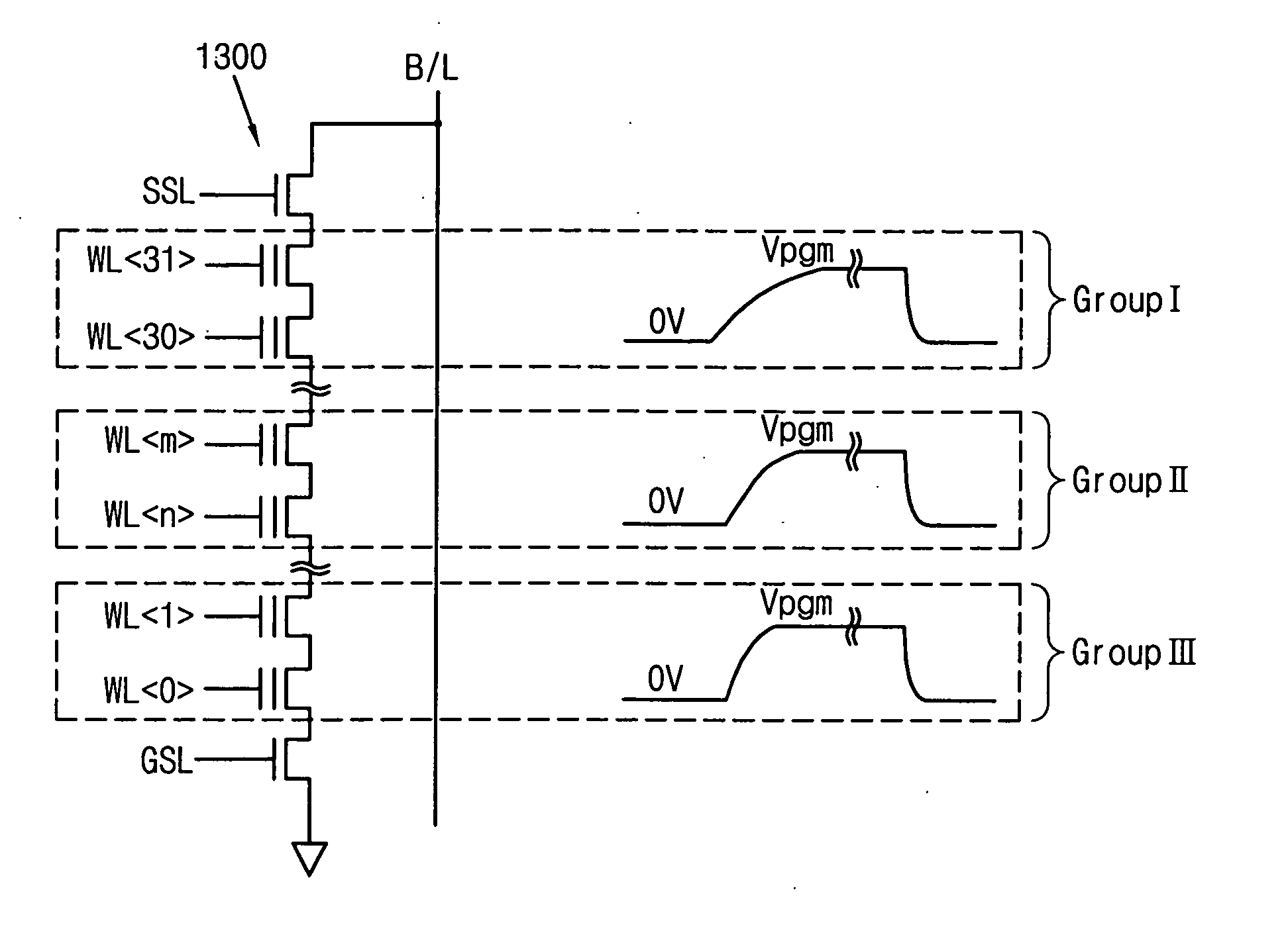
[0068]FIG. 19 shows a detailed block diagram of a word line voltage generator 1900. Word line voltage generator 1900 includes a voltage ladder 1920, a step voltage controller 1940, and a time controller 1960. Voltage ladder 1920 receives a sequence of voltage pulses VPGM1, and produces therefrom a plurality of voltages, V0, V1, V2, . . . , Vn-1. Time controller 1960 outputs a clock signal having a plurality of substantially equal time periods. Step voltage controller 1940 receives the clock signal from time controller 1960 and selects a voltage from voltage ladder 1920 in each of a plurality of time periods to control the slope of at least one of the voltage pulses in response to a ROW address corresponding to the selected word line. That is, step voltage controller 1940 sets a magnitude of the voltage in each clock period according to the ROW address of the selected word line, and thereby controls a slope (rise time) of the voltage pulse according to the position of the selected wo...
second embodiment
[0070]FIG. 21 shows a detailed block diagram of a word line voltage generator 2100. Word line voltage generator 2100 includes a voltage ladder 2120, a step voltage controller 2140, and a time controller 2160. Voltage ladder 2120 receives a sequence of voltage pulses VPGM1, and produces therefrom a plurality of voltages, V0, V1, V2, . . . , Vn-1. Time controller 2160 outputs a clock signal having a plurality of time periods. Step voltage controller 2140 receives the clock signal from time controller 2160 and in response thereto increments the voltage from voltage ladder 2120 by a predetermined amount in each of the plurality of time periods. Beneficially, time controller 2160 sets the time periods to control the slope of at least one of the voltage pulses in response to a row address corresponding to the selected word line. That is, time controller 2160 sets a time period of each clock period according to the ROW address of the selected word line, and thereby controls a slope (rise t...
third embodiment
[0073]FIG. 23 shows a detailed block diagram of a word line voltage generator 2300. Word line voltage generator 2300 includes a pulse voltage generator (not shown), a word line slope controller 2320, a multiplexer 2340, and a word line detector 2360. The pulse voltage generator generates a first sequence of voltage pulses VPGM1 to be applied to a selected word line for programming memory cells of a nonvolatile memory cell array (also not shown). Beneficially, the pulse voltage generator outputs the first sequence of voltage pulses according to the incremental step pulse program (ISPP) technique. Word line slope controller 2320 receives the first sequence of voltage pulses VPGM1 and controls the slope of at least one of the voltage pulses VPGM1 of the first sequence to thereby generate a second sequence of voltage pulses VPGM2. Beneficially, the first and second sequences of voltage pulses VPGM1 and VPGM2 may be any of the pairs of sequences shown in any of FIGS. 14-16 above. Multipl...
PUM
 Abstract
Description
Claims
Application Information
 - R&D
- Intellectual Property
- Life Sciences
- Materials
- Tech Scout
- Unparalleled Data Quality
- Higher Quality Content
- 60% Fewer Hallucinations
Browse by: Latest US Patents, China's latest patents, Technical Efficacy Thesaurus, Application Domain, Technology Topic, Popular Technical Reports.
© 2025 PatSnap. All rights reserved.Legal|Privacy policy|Modern Slavery Act Transparency Statement|Sitemap|About US| Contact US: help@patsnap.com


