Plasma source and applications thereof

a technology which is applied in the field of plasma source and plasma treatment, can solve the problems of rapid recombination of reactive species, source of contamination in cell culture, and difficulty in developing such plasma sources

Active Publication Date: 2007-02-08
MCGILL UNIV
View PDF8 Cites 154 Cited by
  • Summary
  • Abstract
  • Description
  • Claims
  • Application Information

AI Technical Summary

Benefits of technology

[0021] More specifically, there is provided a low-power atmospheric pressure plasma source, comprising a plasma-forming region; an excitation region located downstream of the plasma-forming region; and a narrow converging plasma exit; wherein a plasma-forming gas is injected in the plasma-forming region at a flow rate of a few SLM and a source reactive species is injected in the excitation region, the source producing a narrow plasma jet through the narrow converging plasma exit.
[0022] There is further provided a plasma-assisted treatment system, comprising a low-power atmospheric pressure plasma source, the source comprising a plasma-forming region; an excitation region located downstream of the plasma-forming region; and a narrow converging plasma exit; wherein a plasma-forming gas is injected in the plasma-forming region at a flow rate of a few SLM and a source reactive species is injected in the excitation region, the source producing a narrow plasma jet through the narrow converging plasma exit.
[0023] There is further provided a method for cell modification using a low-power atmospheric pressure plasma source, the source comprising a plasma-forming region; an excitation region located downstream of the plasma-forming region; and a narrow converging plasma exit; wherein a plasma-forming gas is injected in the plasma-forming region at a flow rate of a few SLM and a source reactive species is injected in the excitation region, the source producing a narrow plasma jet through the narrow converging plasma exit.
[0024] Other objects, advantages and features of the present invention will become more apparent upon reading of the following non-restrictive description of specific embodiments thereof, given by way of example only with reference to the accompanying drawings.

Problems solved by technology

The development of such plasma sources is not without challenges.
The main challenges include for example 1) the difficulty to sustain a stable and uniform glow discharge over large surface areas in film deposition and surface functionalization; 2) the need to maintain a high degree of non-thermal equilibrium to minimize the thermal load to the substrates of interest, while maintaining a high degree of chemical reactivity and 3) the extremely rapid recombination of the reactive species in the plasma afterglow when a torch configuration is used.
First, it has traditionally been used on glass or silicon surfaces, and the chemicals used in the process can accelerate the degradation of the polymers used as biomaterials (Miller C, Shanks H, Witt A, Rutkowski G and Mallapragada S 2001 Biomaterials 22 1263-1269) and introduce a source of contamination in cell culture.
Secondly, masks are costly, and give only one pattern.
Moreover, the masking process does not work well on curved surfaces.
(Schroder K, Meyer-Plath A, Keller D and Ohl A 2002 Plasmas and Polymers 7 103-125) have been successful in plasma micropatterning directly through a mask without using the chemical resist, however, they found that the mask was sensitive to handling and heat.
Technologies currently used to permeabilize cells include capillary microinjection, surfactants and electroporation, whose primary limitations are low throughput, cell death, and the need for cells in suspension, respectively.
Inducing cell death restricts time dependent studies, while the trypsinization required to produce a cell suspension disrupts cell adhesion proteins, limiting the study of certain cell processes.

Method used


Image

  • Plasma source and applications thereof
  • Plasma source and applications thereof
  • Plasma source and applications thereof

Examples


Embodiment Construction

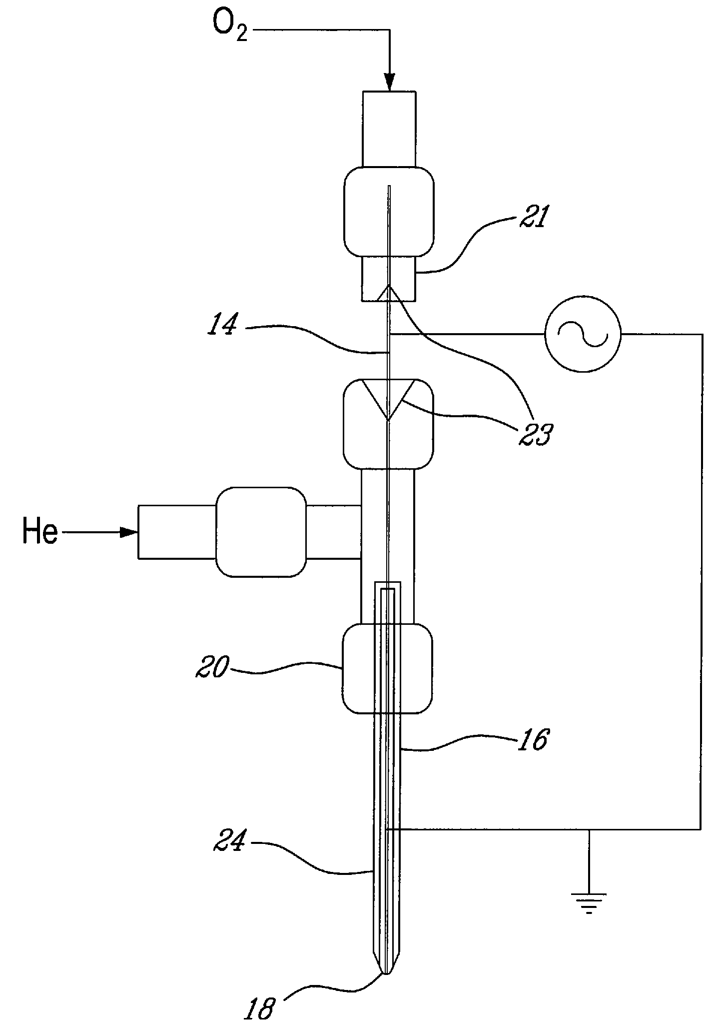
[0039]FIG. 1 of the appended drawings illustrates a plasma source according to an embodiment of a first aspect of the present invention.

[0040] The source comprises a powered electrode 14 and a ground electrode 24.

[0041] The powered electrode 14 is a stainless steel capillary tube for example, with typical inside and outside diameters of 0.0070±0.0005″ (0.1778±0.0127 mm) and 0.0140±0.0005″ (0.3556±0.0127 mm), respectively. The small outside diameter of the powered electrode 14 allows for the local enhancement of the electric field and thus, a considerable reduction of the breakdown voltage requirement.

[0042] The powered electrode 14 is centered in a quartz confinement tube 16 acting as a dielectric barrier. Typically, the confinement tube 16 has an internal diameter of 2 mm, and an exterior diameter of 4 mm, and the downstream end of the tube is shaped into a converging nozzle 18 of an ending diameter of 500 μm or less for example. An electrically conductive layer, such as silver ...


PUM


Abstract

A low-power atmospheric pressure plasma source, comprising a plasma-forming region for injection of a plasma-forming gas; an excitation region for injection of a source reactive species downstream of the plasma-forming region; and a narrow converging plasma exit for producing a narrow plasma jet, the source being electrically decoupled from a substrate under treatment by the plasma jet. The present source may found applications for example for skin treatment, etching of skin cancer cells, detachment of cells, removal of skin pigmentation and deposition of temporary organic films.

Description

CROSS REFERENCE TO RELATED APPLICATIONS [0001] This application claims priority on U.S. provisional application No. 60 / 705,443, filed on Aug. 5, 2005. All documents above and below are herein incorporated by reference.FIELD OF THE INVENTION [0002] The present invention relates to a plasma source and plasma treatment. More specifically, the present invention is concerned with a miniature atmospheric pressure plasma source and applications thereof. BACKGROUND OF THE INVENTION [0003] Plasmas, or ionized gases made up of excited atoms, ions, radicals and electrons, are widely used for modification of surfaces without affecting bulk properties of samples. Plasma treatments have been developed and used for more than 30 years in the microelectronics and textile industries, biomedical, environmental, materials and chemical process engineering fields, as well as in surgery. Plasmas offer a high-density source of energy and / or reactive species. [0004] Atmospheric-pressure plasmas are used in ...

Claims


Application Information

Patent Timeline
Patent Type & Authority Applications(United States)
IPC IPC(8): H01T23/00H01J27/00
CPCH05H1/24H01T23/00A61C19/063H05H1/475H05H1/34
Inventor COULOMBE, SYLVAINYONSON, SARALEVEILLE, VALERIELEASK, RICHARD
Owner MCGILL UNIV
Why Eureka
Try Eureka