Optical probe for Raman scattering from arterial tissue

Inactive Publication Date: 2007-02-15
NEWTON LAB
View PDF14 Cites 31 Cited by
  • Summary
  • Abstract
  • Description
  • Claims
  • Application Information

AI Technical Summary

Benefits of technology

[0005] The convex reflective surface of the axicon disperses the excitation light azimuthally but not axially, providing near complete coverage of the inner wall of the artery. The central lumen has sufficient diameter to allow for the passage of a balloon catheter and/or guidewire for occluding the artery directly in front of the distal tip. A saline flush through the

Problems solved by technology

However, due to the weakness of the Raman signals returning from the tissue, it remains difficult to

Method used


Image

  • Optical probe for Raman scattering from arterial tissue
  • Optical probe for Raman scattering from arterial tissue
  • Optical probe for Raman scattering from arterial tissue

Examples


Embodiment Construction

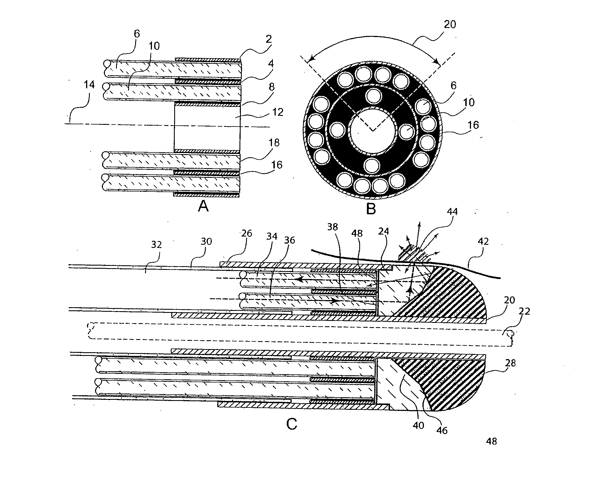
[0012]FIG. 1A shows a ferrule including three concentric thin-wall tubes of drawn stainless steel which hold the optical fibers in their correct radial and azimuthal positions. The outer tube, 2, and middle tube, 4, constrain the receiver fibers, 6, to the outer radius closest to the artery wall. The middle tube, 4, and central tube, 8, constrain the excitation fibers, 10, to the inner radius. The lumen of the central tube, 8, is centered on the axis of the probe, 14, and is kept free for the passage of a guide wire. The fibers, 6 and 10, and the ferrule tubes, 2, 4 and 8, are epoxied together, 16, into a unit so that the ends of the fibers can be optically polished together to form a single plane, 18.

[0013]FIG. 1B shows an end view of the completed ferrule indicating how the excitation fibers, 10, and receiver fibers, 6, are arranged within a given quadrant, 20. The Raman excitation source is a laser, so that only a single fiber, 10, is necessary to deliver excitation light to a g...


PUM


Abstract

The present invention related to a Raman artery probe diagnostic system and a method of using the system for the diagnosis of vascular disease. A side looking catheter having light delivery and collection optical fibers can deliver infrared light in a radial direction from the catheter to diagnose atherosclerotic plaques in the coronary arteries. A guidewire or guide catheter can be used to deliver the catheter to the region of interest within the artery to evaluate vulnerable plaques.

Description

CROSS REFERENCE TO RELATED APPLICATIONS [0001] This application claims the priority of U.S. Provisional Application No. 60 / 686,601 filed Jun. 2, 2005 entitled, OPTICAL PROBE FOR RAMAN SCATTERING FROM ARTERIAL TISSUE, the whole of which is hereby incorporated by reference herein.BACKGROUND OF THE INVENTION [0002] Optical methods have been developed for the measurement of tissue. Raman spectroscopy, due to its ability to discern the chemical components of tissue has been developed to aid in the diagnosis of disease. Optical fiber probes have been used in conjunction with this method to deliver and collect light in regions of the human body to provide in vivo diagnostic procedures. Small diameter catheters have been proposed for use within the coronary arteries in order to diagnose atherosclerotic lesions. [0003] Spectrometers and detectors are used to acquire spectral data that is processed to provide diagnostic information. However, due to the weakness of the Raman signals returning ...

Claims


Application Information

Patent Timeline
IPC IPC(8): A61B6/00
CPCA61B5/0071A61B5/0075A61B5/0086G01N21/65G01J3/02G01J3/0218G01J3/44A61B5/02007
Inventor FULGHUM, STEPHEN
Owner NEWTON LAB
Why Eureka
Try Eureka