Particulate polymeric material

Inactive Publication Date: 2007-02-22
EASTMAN KODAK CO
View PDF7 Cites 34 Cited by
  • Summary
  • Abstract
  • Description
  • Claims
  • Application Information

AI Technical Summary

Benefits of technology

[0016] The process of the present invention provides a polymeric particulate material that is capable of being coated onto a support to a form a receiving layer for an ink-jet rec

Problems solved by technology

As the component materials are relatively dense, large masses of material are needed and the layers are often prone to cracking and brittleness.
The main problem with this type of receiver is that the diffusion process is relatively slow and the receivers can take a considerable time before they appear dry.
Methods for making porous polymer materials

Method used


Image

  • Particulate polymeric material
  • Particulate polymeric material
  • Particulate polymeric material

Examples


Example

Example 1

PolyHIPE Formation

[0092] Styrene (9 ml) and divinyl benzene (1 ml, 55% purity) were mixed with sorbitan monooleate (3 ml) in a 500 ml wide-mouth plastic bottle and stirred with a Polytron high shear mixer at 4000 rpm under a blanket of nitrogen gas. A solution of calcium chloride (1 g) and potassium persulfate (0.4 g) in water (90 ml) that had been deoxygenated by bubbling nitrogen through it for 20 minutes was then added over approximately 30 minutes by peristaltic pump to the stirred monomers. During this addition, the stirrer head was raised as the volume in the bottle increased to ensure efficient mixing. After addition was complete, the mixture was stirred a further 10 minutes at 5000 rpm.

[0093] The HIPE formed was coated at 100 μm thickness onto aluminium foil, which was then laminated with a flat polyester sheet and cured in the oven at 70° C. for a minimum of 6 hours. The polyester laminate was removed and the coating allowed to dry at 60° C. for 2 hours. The res...

Example

Example 2

PolyHIPE Formation

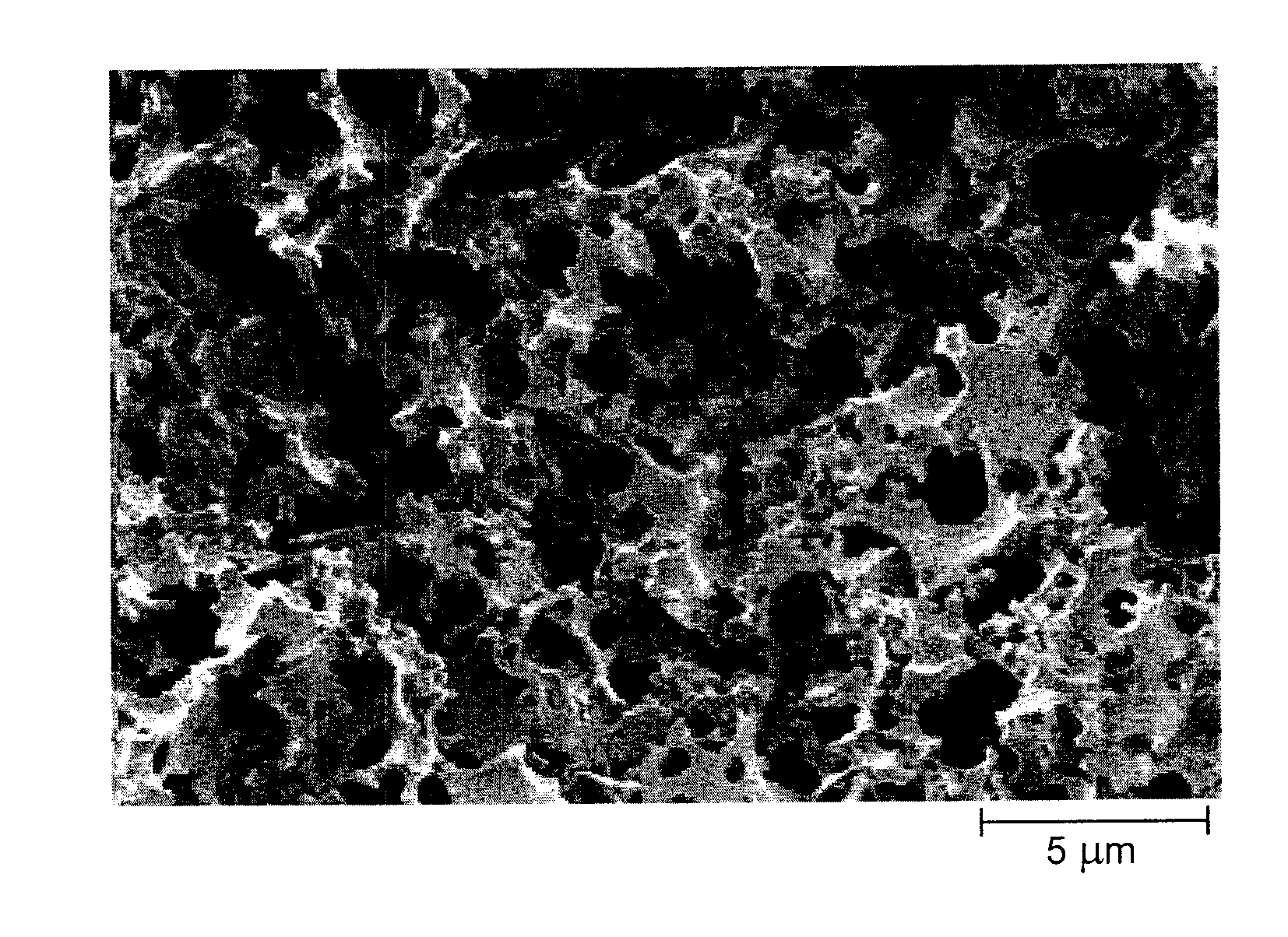
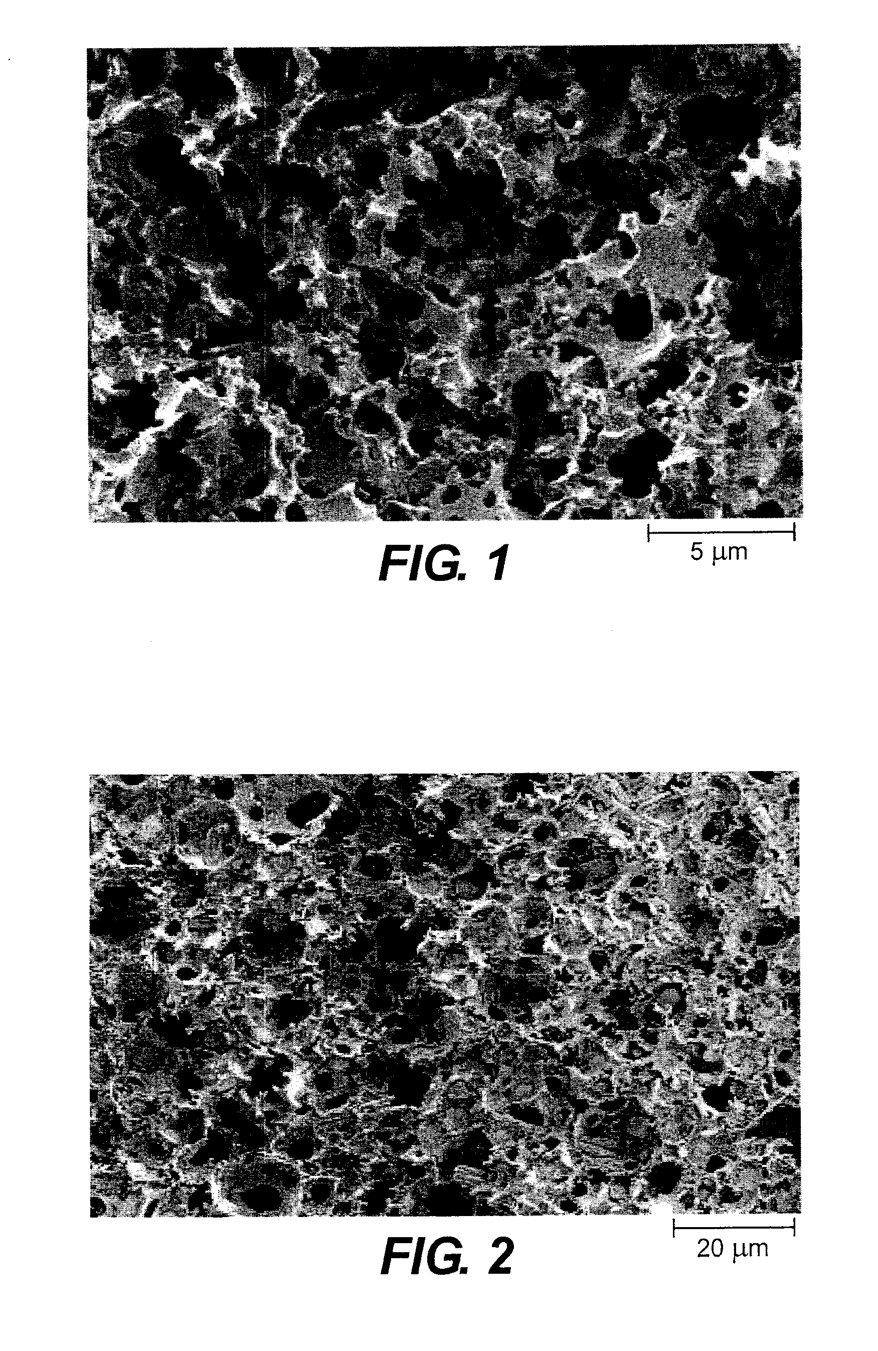
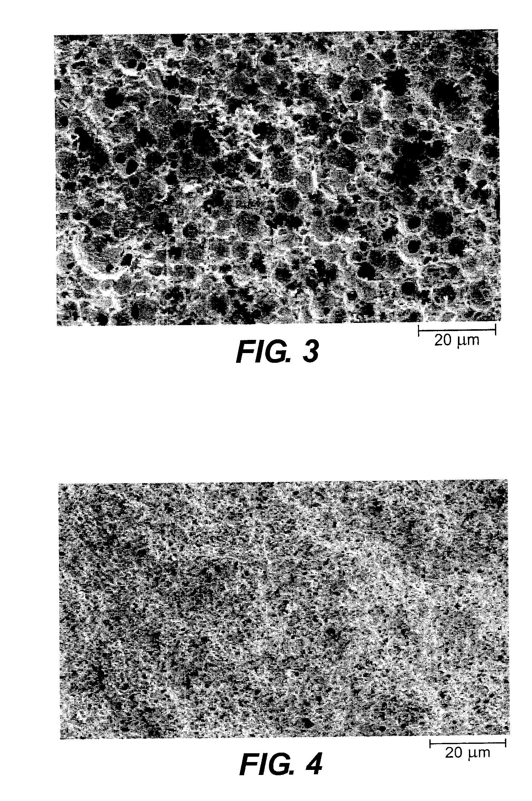
[0094] The effect of high shear stirring on the polymer structure was observed by preparing three polyHIPE samples using the method of Example 1, except that each sample was prepared using a different shear rate. During the addition of the aqueous phase, the Polytron mixer was run at 2000, 4000 and 6000 rpm. SEM of the resultant samples clearly shows the reduction in size of the pore structure with increasing shear rate—see FIG. 2 (shear rate 2000 rpm), FIG. 3 (shear rate 4000 rpm) and FIG. 4 (shear rate 6000 rpm). FIG. 5 shows a graphical relationship between shear rate and mean pore diameter.

Example

Example 3

PolyHIPE Formation

[0095] Styrene (4.5 ml), divinyl benzene (0.5 ml, 55% purity) and sorbitan monooleate (3 ml) were dissolved in toluene (5 ml) and degassed with nitrogen bubbling for 20 minutes. This mixture was stirred at 300 rpm with a 6-bladed impeller (38 mm diameter) while a nitrogen degassed solution of calcium chloride (1 g) and potassium persulfate (0.2 g) was added over approximately 1 hour by peristaltic pump. Stirring was continued for a further 5 minutes and then a sample of the emulsion was placed in an oven at 60° C. for 24 hours to cure, followed by heating under vacuum at 75° C. to dry. From SEM (FIG. 6) it can be seen that not only has the typical polyHIPE structure been formed but that the polystyrene itself is porous.


PUM

PropertyMeasurementUnit
Pore sizeaaaaaaaaaa
Percent by massaaaaaaaaaa
Lengthaaaaaaaaaa

Abstract

A polymeric particulate material suitable for use in an ink-jet receiver is prepared by generating an emulsion comprising a first phase having a first carrier fluid and a second phase having a second carrier fluid, said first and second carrier fluids being immiscible; carrying out a first treatment to at least one component of the first phase to form and/or maintain a skeletal structure of the treated at least one component of the first phase; carrying out a second treatment to the second phase to substantially remove the carrier fluid thereby generating a large capacity porous structure defined by the skeletal structure; and mechanically dividing (e.g. milling) the skeletal structure. A coating of the particles is capable of rapid uptake of large quantities of ink, especially when formed using a high internal phase water-in-oil emulsion.

Description

FIELD OF THE INVENTION [0001] The present invention relates to a novel method of making particles of polymeric material and more particularly to their use in manufacturing ink-jet receivers. The invention is particularly concerned with improved ink-receiving layers having rapid ink uptake and large capacity. More specifically, the present invention relates to the use of emulsions to generate porous polymer structures from which particles formed therefrom may be used in the manufacture of porous ink-jet receivers. BACKGROUND OF THE INVENTION [0002] Ink-jet receivers are generally classified in one of two categories according to whether the principal component material forms a layer that is “porous” or “non-porous” in nature. Many commercial photo-quality porous receivers are made using a relatively low level of a polymeric binder to lightly bind inorganic particles together to create a network of interstitial pores which absorb ink by capillary action. These receivers can appear to d...

Claims


Application Information

Patent Timeline
IPC IPC(8): C03C17/00B41M5/52
CPCB41M5/5254C08F212/08C08L29/04C09D125/06C08F2/24C08L2666/04C08F212/36
Inventor HIGGINS, JOHN M.NEWINGTON, IAN M.
Owner EASTMAN KODAK CO
Why Eureka
Try Eureka