
Method of producing composite members having increased strength

Inactive Publication Date: 2007-03-01
ECOPURO LLC
View PDF8 Cites 17 Cited by
  • Summary
  • Abstract
  • Description
  • Claims
  • Application Information

AI Technical Summary

Benefits of technology

[0025] The conformable core material is injected into and around internal structural support members of an extruded member. Preferably, while the member is being extruded, the core material is injected to replace air voids within the member. The injection of conformable structural core material at the same time and same rate as the structural member is being extruded produces significant improvements by increasing load bearing capacity, stability and overall strength and by improving economic feasibility. For example, a rigid polyurethane foam is approximately 10 times less expensive per volume than PVC. Therefore, by replacing some interior volume of an extruded member with foam, the PVC volume is reduced while maintaining the same structural strength or greater. Therefore, the injection of a conformable foam results in a significant cost savings. In some applications, the injectable conformable structural core material may be applied to an extruded member that has been previously cured.
[0037] Solid core materials can be made from high-density polyurethane, polyureas and epoxy materials etc., having high strength and fast cure times. These materials may be filled with fillers or micro spheres to produce high strength injectable core materials.

Problems solved by technology

The cross-section of the members may also be very complex, including internal support structures and / or having an irregular periphery.
One drawback associated with existing extruded composite structural building materials is that existing materials lack the strength necessary to directly compete with or replace structural wood, e.g., various sized wood beams, i.e., 2×4, 2×6, 2×8, 4×4, 4×6, 4×8, etc.
However, composite materials typically still require wood support structures for structural strength.
The addition of wood particles to plastic also results in some undesirable characteristics.
For example, wood particles may rot and are susceptible to fungal attack, wood particles can absorb moisture, wood particles are on the surface of a WPC member can be destroyed by freeze and thaw cycling, wood particles are susceptible to absorbing environmental staining, e.g., from tree leaves, wood particles can create pockets if improperly distributed in a WPC material, which may result in a failure risk that cannot be detected by visual inspection, and wood particles create manufacturing difficulties in maintaining consistent colors because of the variety of wood species color absorption is not consistent.
As a result, the wood particles on the surface tend to undergo environmental bleaching.
Consequently, repairing a deck is difficult due to color variation after 6 months to a year of sun exposure.
Problems associated with typical pre-formed core materials include difficulties associated with incorporating the materials into the extrusion process due to the pre-formed shape of the materials.
Therefore increasing strength by fiber orientation is not applicable to an extrusion process.
However structural mechanical properties of the foam core tend not to be addressed.
One problem that may occur when a core material and a structural material are not compatible both chemically and physically is delamination.
Chemical and physical incompatibility can result in composite structures that suffer structural failures when the core material and the structural material separate from one another.
As discussed above, even though increasing load bearing capacity, stability and strength can be increased by engineering improvements with new resins / plastics, fibers / fillers and internal structural support members, load bearing capacity is still limited by the mechanics of the extrusion process.
Additionally, other applications, such as aerospace applications, utilize composite structures and have had to contend with problems associated with delamination of core materials and structural materials.

Method used


Image

  • Method of producing composite members having increased strength
  • Method of producing composite members having increased strength
  • Method of producing composite members having increased strength

Examples


Embodiment Construction

[0052] Before explaining the present invention in detail, it is important to understand that the invention is not limited in its application to the details of the embodiments and steps described herein. The invention is capable of other embodiments and of being practiced or carried out in a variety of ways. It is to be understood that the phraseology and terminology employed herein is for the purpose of description and not of limitation.

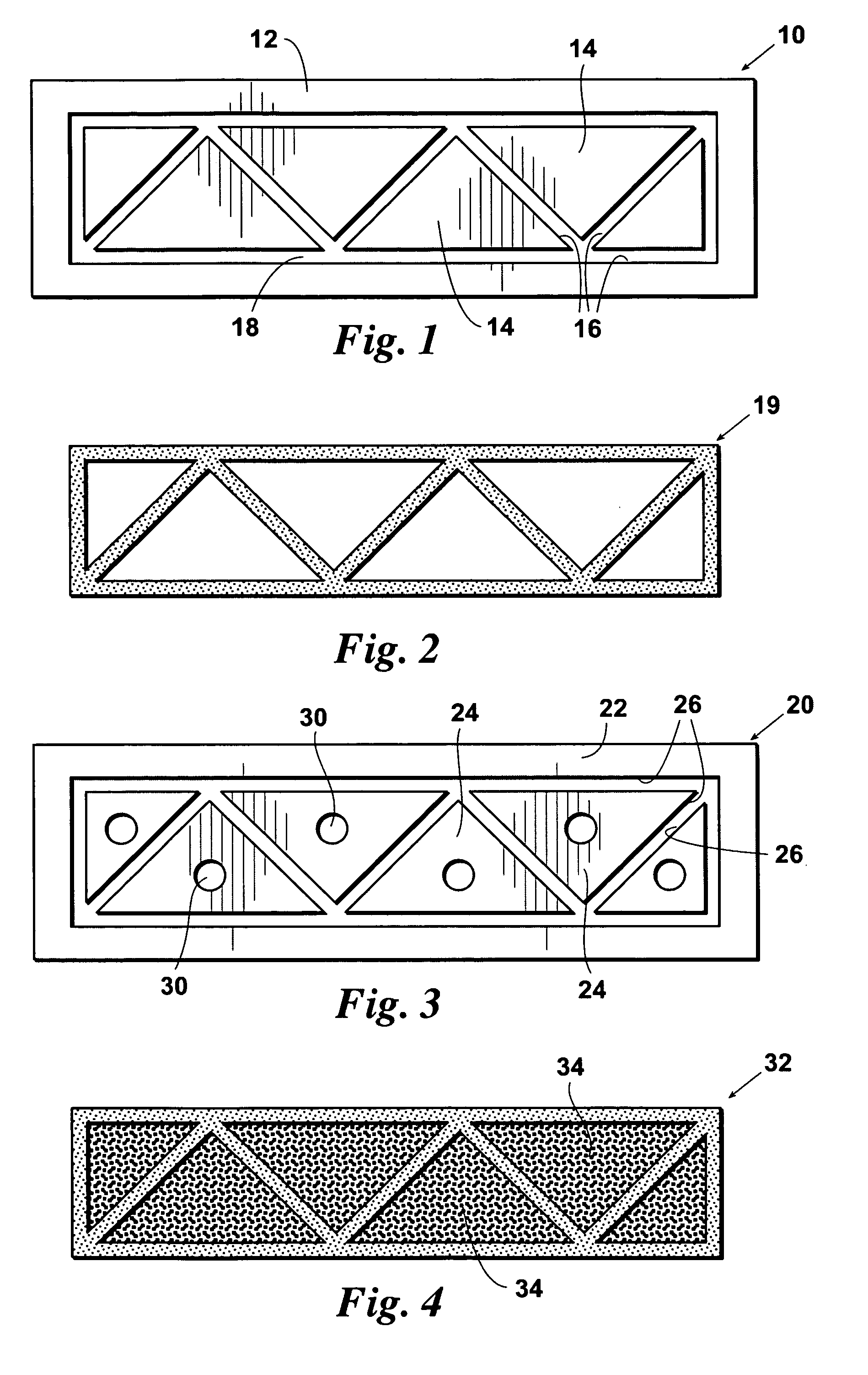
[0053] Referring now to FIG. 1, a cross-section of prior art extrusion die 10 is shown. Extrusion die 10 includes external die element 12 and internal die elements 14 that define die walls 16. Die walls 16 define channels 18 through which a molten material is forced. Once the molten material is forced out of the die 10, the material cools, resulting in an extruded member, e.g., extruded member 19, shown in cross-section in FIG. 2.

[0054] Referring now to FIG. 3, an improved extrusion die 20 is shown. Extrusion die 20 includes external die element 22...


PUM

PropertyMeasurementUnit
Percent by massaaaaaaaaaa
Temperatureaaaaaaaaaa

Abstract

This invention relates to extruded composite materials specifically focusing on the increasing load bearing capacity and the overall strength of composites. Injectable conformable structural core materials are used to replace foam cells inside extruded composite materials thereby increasing the overall load bearing stability and strength. The core materials are tailored to have a desired CTE with respect to the structural materials. The core materials may also incorporate fibers and solid structural fillers for increasing the strength of the composite member. The objective is to enable composite materials to have the highest structural load bearing capability possible so that these technologies can be used as the replacement of wood, in aerospace applications and for other purposes.

Description

CROSS REFERENCE TO RELATED APPLICATION [0001] This application claims the benefit of U.S. Provisional Application No. 60 / 709,628, which application was filed with the Patent and Trademark Office on Aug. 19, 2005, which application is hereby incorporated by reference.FIELD OF THE INVENTION [0002] This invention relates generally to structures having structural core materials inside of a composite matrix. More particularly, the invention relates to extruded composite building materials having a selected core material tailored to increase the strength of the extruded member. BACKGROUND OF THE INVENTION [0003] An extrusion process is one of the most economic methods of manufacturing to produce engineering structural materials. Typically, an extrusion process is used to manufacture lengths of extruded members having a uniform cross-section. The cross-section of the members may be of various simple shapes such as circular, annular, or rectangular. The cross-section of the members may also...

Claims


Application Information

Patent Timeline
IPC IPC(8): B29C47/06B29C47/12B29C47/92B05D5/00B05D3/12B29C44/20B29C48/07B29C48/11B29C48/12B29C48/30B29C48/92
CPCB29C44/128B29C44/186B29C44/3411B29L2031/60B29C47/12B29C47/128B29K2105/04B29C47/0028B29C48/11B29C48/304B29C2948/92561B29C2948/926B29C2948/92761B29C2948/92952B29C2948/9298B29C48/07B29C48/12B05D3/12B05D5/00B29C44/20
Inventor JOHNSON, WILLIAM L. SR.
Owner ECOPURO LLC
Learn More