Holding unit, assembly system, sputtering unit, and processing method and processing unit

a technology of sputtering unit and holding unit, which is applied in the field of holding unit, assembly system, sputtering unit, processing method and processing unit, can solve the problems of limited manufacturing of units (components) and relative difficulty in generating steric fine structure that does not have a deposited structure, and the inability to mass-produce such a uni

Active Publication Date: 2007-03-01
NIKON CORP
View PDF10 Cites 41 Cited by
  • Summary
  • Abstract
  • Description
  • Claims
  • Application Information

AI Technical Summary

Benefits of technology

[0015] According to this unit, the object can be set at a desired position that corresponds to the position of the conductive material to which current is supplied, and the object can be held in the state. Further, attraction such as the friction force or the like generated between the object and the base when the position of the object is set can be reduced.
[0035] According to this unit, because the magnetic suction mechanism that magnetically suctions the magnetic substance is arranged in the first base and the suction unit that vacuum suctions a portion that is not magnetically suctioned by the magnetic suction mechanism is arranged in the second base, by moving at least one of the first base and the second base in a state where the object is held between the first base and the second base, it becomes possible to apply processing to the object according to the movement direction.

Problems solved by technology

However, on the other hand, because the processing method of the silicon wafer is limited to the method in which resist coating, exposure, development, etching and doping are sequentially performed and the method has a structural limit of depositing a structural object on a plane and the like, it is relatively difficult to generate a steric fine structure that does not have a deposited structure, and the units (components) that can be manufactured are limited.
Recently, there are cases at a research level where a worker builds a micromachine by assembling fine components using a manipulator; however, the technology for mass-producing such a unit does not exist.
Even if research cases on key factors such as a micromotor or internal combustion are publicized, research cases as well as the mass-production technology for combining such factors are limited in the present situation.
However, under present circumstances, there are no signs that show progress in such an approach.
The reason for this is attributed to the fact that there is more difficulty in handling the components (assembling, applying secondary processing) that are scaled down than the difficulty in scaling down the components.

Method used


Image

  • Holding unit, assembly system, sputtering unit, and processing method and processing unit
  • Holding unit, assembly system, sputtering unit, and processing method and processing unit
  • Holding unit, assembly system, sputtering unit, and processing method and processing unit

Examples


first embodiment

A First Embodiment

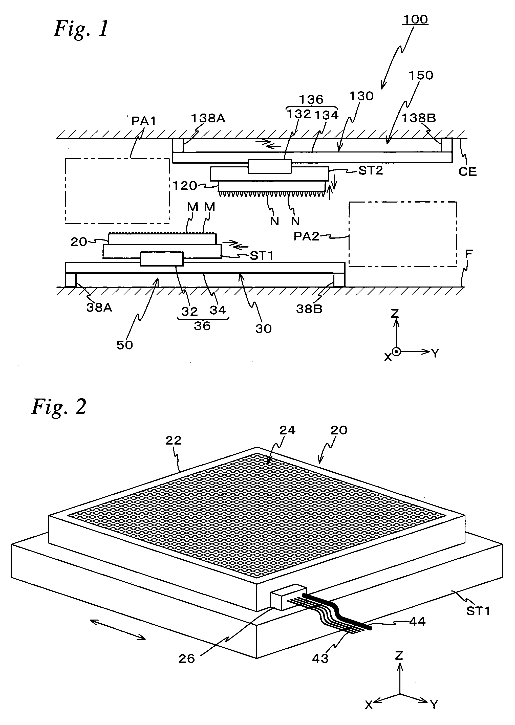
[0067] A first embodiment of the present invention will be described below, referring to FIGS. 1 to 9. FIG. 1 shows an assembly system 100 related to the first embodiment. Assembly system 100 is a system for applying processing to a fine structure such as a MEMS device, an LSI or the like.

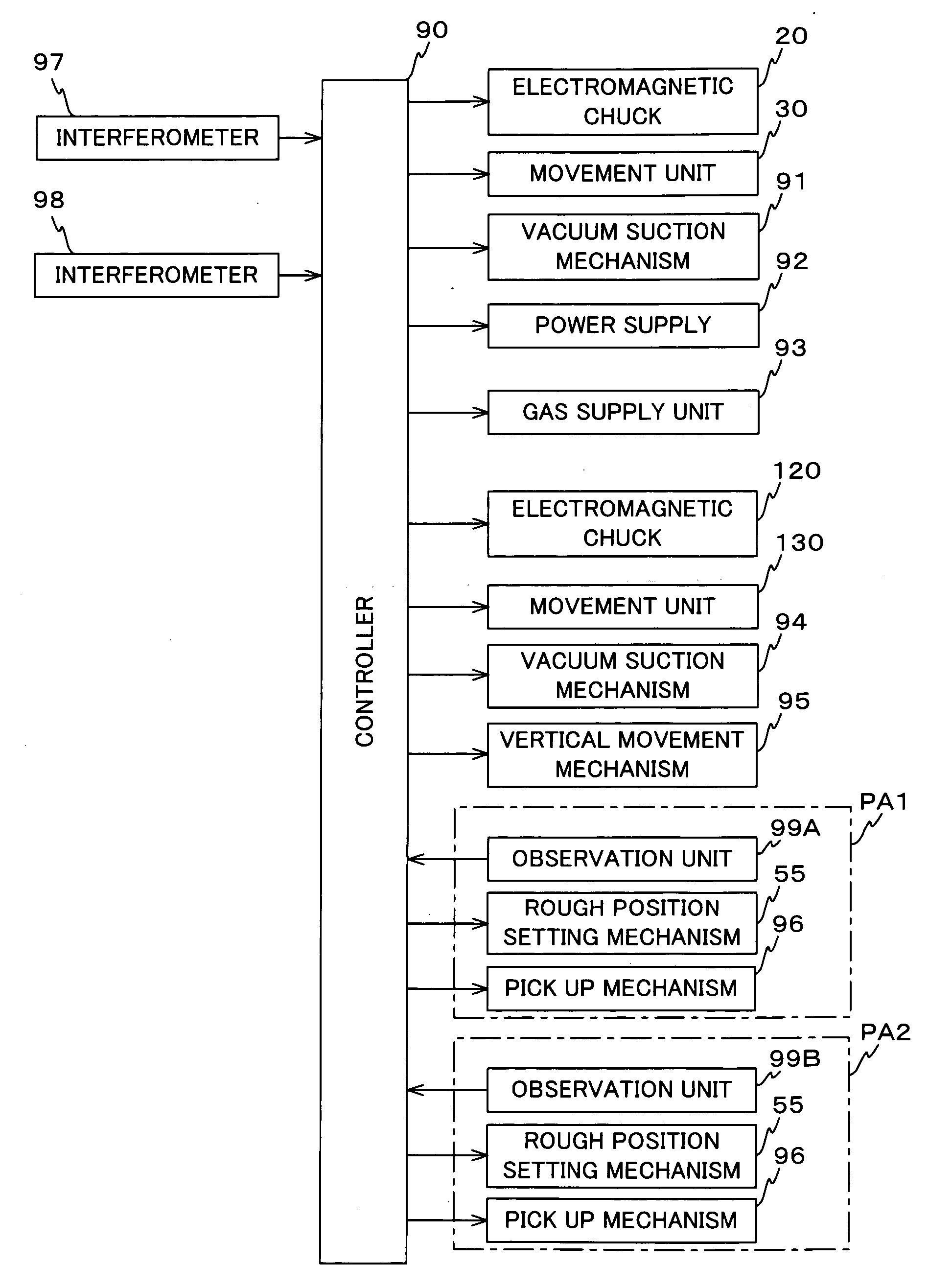
[0068] Assembly system 100 is installed entirely in, for example, a housing that has a floor surface F and a ceiling surface CE, and the system is equipped with a first holding unit 50 installed on floor surface F of the housing, a second holding unit 150 supported hanging from ceiling surface CE of the housing in a state vertically facing first holding unit 50, and pre-alignment units PA1 and PA2 that respectively correspond to first holding unit 50 and second holding unit 150.

[0069] The first holding unit 50 also includes a stage (a moving body or a table) ST1, an electromagnetic chuck 20 held on the upper surface of stage ST1, and a movement unit 30 that moves stage ST1 at le...

second embodiment

A Second Embodiment

[0118] Next, a second embodiment of the present invention will be described, referring to FIGS. 11A to 12.

[0119]FIG. 11A shows a schematic configuration of the second embodiment in the present invention. As is obvious from FIG. 11A, the point where electromagnetic chuck 20 and electromagnetic chuck 120 are arranged is the same as the first embodiment previously described, however, the point where a power supply 70 for arc welding connects to electromagnetic chuck 120 is different from the first embodiment. Electromagnetic chuck 120 is made movable in the vertical direction (the Z-axis direction) using a vertical movement mechanism 95 (refer to FIG. 12) as in the first embodiment.

[0120] In the embodiment, for example, objects M (magnets are arranged in part of the objects as in the first embodiment) that have a rough cubic shape are held in a state where objects M are positioned spaced evenly apart using electromagnetic chuck 20, and objects M are also held in a ...

third embodiment

A Third Embodiment

[0128] Next, a processing unit 80 related to a third embodiment of the present invention will be described, referring to FIGS. 13A to 14C. In the third embodiment, electromagnetic chuck 20 used in the first and second embodiments is used as a constituent part of processing unit 80.

[0129] As is shown in FIG. 13A, processing unit 80 of the third embodiment is equipped with electromagnetic chuck 20 and a vacuum chuck 220 arranged facing electromagnetic chuck 20.

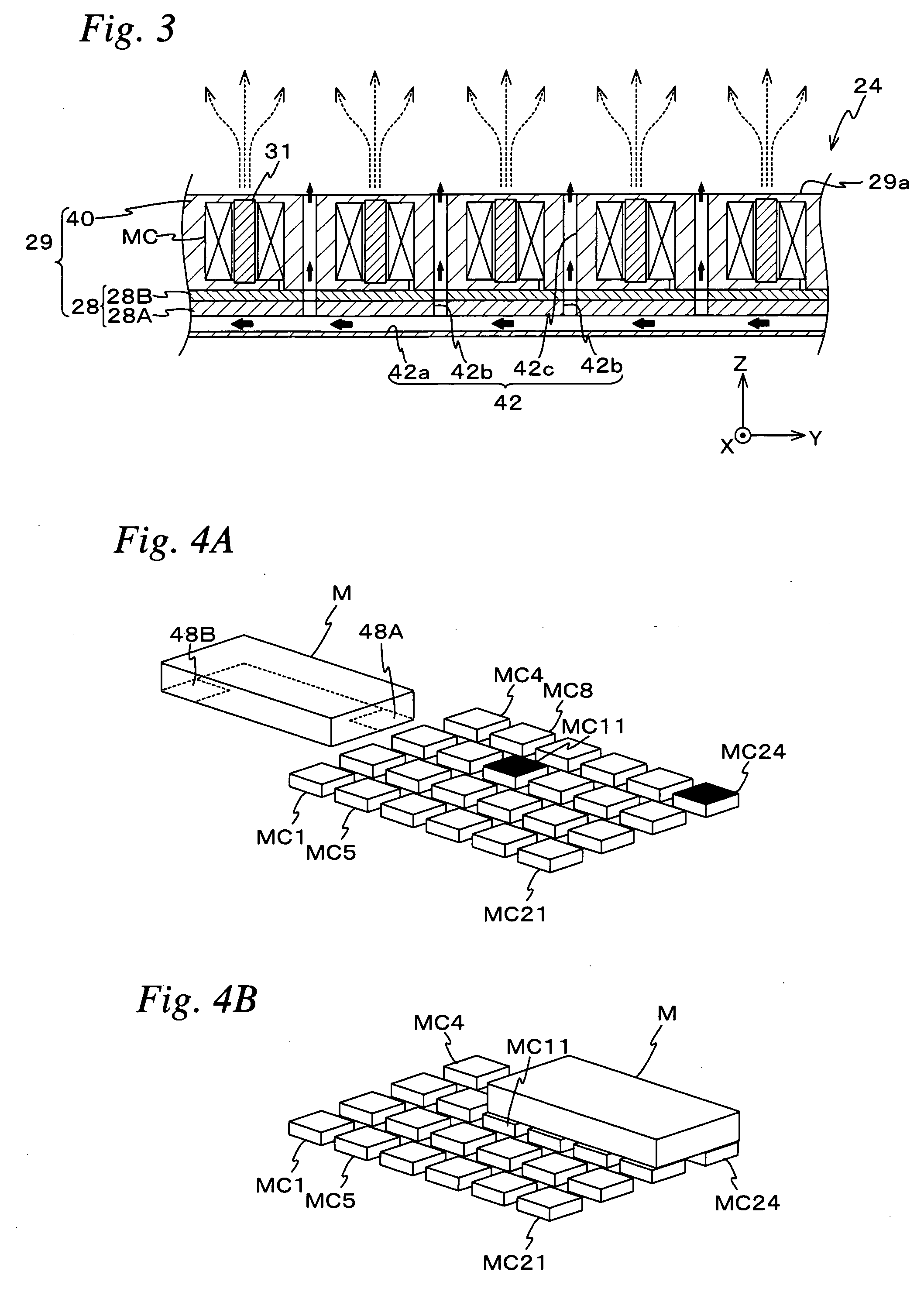
[0130] Although the unit is arranged upside down, electromagnetic chuck 20 is configured similar to the first embodiment and is equipped with coil holding board 29 and a plurality of microcoils MC arranged on coil holding board 29. Electromagnetic chuck 20 is movable in the vertical direction (the Z-axis direction) by a vertical movement mechanism, which is similar to the one arranged on the electromagnetic chuck 120 side in the first and second embodiments.

[0131] Vacuum chuck 220 is equipped with a base 222...


PUM

PropertyMeasurementUnit
widthaaaaaaaaaa
widthaaaaaaaaaa
magneticaaaaaaaaaa

Abstract

Because an electromagnetic chuck supplies current to a specific microcoil among a plurality of microcoils and makes an object exert an electromagnetic force working together with a magnet of the object, the object can be held in a state where the object is set at a desired position (a position that corresponds to the microcoil to which current has been supplied) on a base surface. Further, by gas that blows out from a gas supply passage, a levitation force is given to the object, which can reduce effects of a friction force that acts between the object and an upper surface of the electromagnetic chuck when the position of the object is set.

Description

CROSS-REFERENCE TO RELATED APPLICATIONS [0001] This non-provisional application claims the benefit of Provisional Application No. 60 / 727,829 filed Oct. 19, 2005, the disclosure of which is hereby incorporated herein by reference in its entirety.BACKGROUND OF THE INVENTION [0002] 1. Field of the Invention [0003] The present invention relates to holding units, assembly systems, sputtering units, and processing methods and processing units, and more particularly to a holding unit that holds an object which at least partially contains a magnetic substance, an assembly system that uses the holding unit, a sputtering unit that forms a thin film on a base material by making ions collide with a target material in vacuum, a processing method in which the object containing the magnetic substance at least partially is processed and a processing unit that processes the object. [0004] 2. Description of the Related Art [0005] Recently, semiconductor processing technology using micromachining tech...

Claims


Application Information

Patent Timeline
Patent Type & Authority Applications(United States)
IPC IPC(8): G03B27/70G03B27/42G03B27/52
CPCG03F7/70758G03F7/70816Y10T29/49998Y10T29/53961Y10T29/49014
Inventor SHIBAZAKI, YUICHI
Owner NIKON CORP
Why Eureka
Try Eureka