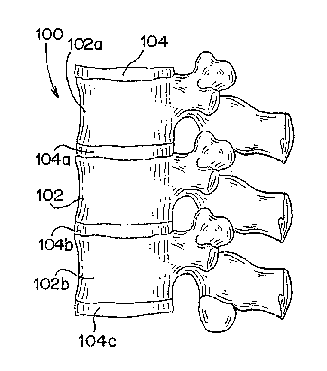
Vertebral compression fractures affect a significant part of the
population, and add significant cost to the health care
system.
The
osteoporosis-weakened vertebrae can collapse during normal activity and are also more vulnerable to injury from shock or other forces acting on the spine.
While the fractures may heal without intervention, the crushed bone may fail to heal adequately.
Commonly, they cause loss of height and a humped back.
In severe cases, the body's
center of mass is moved further away from the spine resulting in increased
bending moment on the spine and increased loading of individual vertebrae.
When
cancer cells spread to the spine, the
cancer may cause destruction of part of the
vertebra, weakening and predisposing the bone to fracture.
Such trauma may result from a fall, a forceful jump, a car accident, or any event that compresses or otherwise stresses the spine past its
breaking point.
However, they often cause a severe “band-like” pain that radiates from the spine around both sides of the body.
It is commonly believed that the source of
acute pain in compression fractures is the result of
instability at the
fracture site, allowing motion that irritates nerves in and around the vertebrae.
Unfortunately, the typical patient is an elderly person.
As a class of patients, the elderly generally do not tolerate extended
bed rest well.
The difficulty of controlling or stopping bone filler flow into injury-sensitive areas increases as the required pressure increases.
If a foraminal leak results, the patient may require surgical decompression and / or suffer
paralysis.
However, in practice it is difficult to consistently attain meaningful and predictable height restoration.
The inconsistent results may be due, in part, to the manner in which the
balloon expands in a compressible media, such as the cancellous tissue within the vertebrae, and the structural orientation of the
trabecular bone within the
vertebra, although there may be additional factors as well.
The weight of the person generates a
compressive load on the disks, but this load is not uniform during typical bending movements.
On the local (or cellular) level, decreased disk height results in increased pressure in the
nucleus, which can lead to a decrease in
cell matrix synthesis and an increase in
cell necrosis and
apoptosis.
In addition, increases in intra-diskal pressure create an unfavorable environment for fluid transfer into the disk, which can cause a further decrease in disk height.
Decreased disk height may also result in significant changes in the overall
mechanical stability of the spine.
With decreasing height of the disk, the
facet joints bear increasing loads and may undergo hypertrophy and degeneration, and may even act as a source of pain over time.
This decrease may lead to
spinal nerve impingement, with associated radiating pain and dysfunction.
The disks that must bear additional loading are susceptible to accelerated degeneration and compromise, which may eventually propagate along the destabilized
spinal column.
However, a sudden decrease in disk volume caused by
surgical removal of the disk or disk
nucleus can heighten the local and global problems noted above.
This loss of disk height can cause non-tensile loading and buckling of the annulus.
The loss of disk height also causes the annular lamellae to delaminate, resulting in annular fissures and rupture of the annulus.
During a total diskectomy, a substantial amount (and usually all) of the volume of the nucleus pulposus is removed and immediate loss of disk height and volume can result.
Even with a partial diskectomy, loss of disk height can ensue.
A challenge of inserting a disk
implant posteriorly is that a device large enough to contact the endplates and slightly expand the
intervertebral space between the endplates must be inserted through a limited space.
This challenge is often further heightened by the presence of posterior osteophytes, which may cause converging or “fish mouthing” of the posterior endplates that results in very
limited access to the disk.
A further challenge in degenerative disk spaces is the tendency of the
disk space to assume a lenticular shape, which requires a relatively larger
implant that often is not easily introduced without causing trauma to the nerve roots.
The size of rigid devices that may safely be introduced into the
disk space is thereby limited.
Cages inserted from the
posterior approach, however, are limited in size by the interval between the nerve roots.
Although disk removal is commonly combined with fusion in the neck, this is not generally true in the
low back (
lumbar spine).
A major obstacle to the successful treatment of spine pain by fusion is the difficulty in accurately identifying the source of a patient's pain.
Vertebral bodies may be compromised due to
disease, defect, or injury.
These prior art devices and the procedures associated therewith have difficulty in maintaining the proper structural scaffolding while a castable material, such as
bone cement, is hardened in the cavity left by the removed
vertebral body.
The maintaining of proper structural scaffolding has been especially difficult in a minimally invasive posterior surgical approaches.

