
Plasma etching apparatus and plasma etching method

a technology of plasma etching and etching apparatus, which is applied in the direction of fluid pressure measurement, instruments, vacuum gauges, etc., can solve the problems of in-plane uniformity of etch rate over a wider area of specimen, increase in specimen size, and in-plane so as to reduce the non-uniformity of cd shift and excellent in-plane uniformity

Inactive Publication Date: 2007-03-15
HITACHI HIGH-TECH CORP
View PDF6 Cites 21 Cited by
  • Summary
  • Abstract
  • Description
  • Claims
  • Application Information

AI Technical Summary

Benefits of technology

[0018] Accordingly, it is a first object of the present invention to provide a plasma etching apparatus that can perform etching with excellent in-plane uniformity and that can reduce the nonuniformity of the CD shift caused by variations in the surface density and to provide a plasma etching method using the plasma etching apparatus.
[0019] It is a second object of the present invention to provide a plasma etching apparatus that can perform etching with excellent in-plane uniformity and a high throughput and to provide a plasma etching method using the plasma etching apparatus.

Problems solved by technology

While the gate etching is performed with such a plasma etching apparatus, an increase in the size of the specimen 1 makes it difficult to achieve in-plane uniformity of the etch rate over a wider area of the specimen 1, the CD shift of the gate etching, and the shape of the gate electrode 7.
This can also cause in-plane nonuniformity of the CD shift.
Furthermore, in-plane nonuniformity of an etchant, such as a chlorine radical or ion or a bromine radical or ion, in the vicinity of the surface of the specimen can cause in-plane nonuniformity of the etch rate, which can in turn cause in-plane nonuniformity of the CD shift.
Thus, in-plane nonuniformity of the oxygen content may cause in-plane nonuniformity of the CD shift.
Thus, in-plane nonuniformity of the concentration of the carbonaceous reaction product may cause in-plane nonuniformity of the CD shift.
However, this technique does not refer to individual control in a plurality of etching steps constituting the etching process.
Furthermore, this technique is insufficient to reduce nonuniformity of the CD shift caused by variations in the surface density.
Thus, the target CD shift cannot be achieved by a continuous plasma discharge throughout the steps.
However, the nonoperating steps decrease the throughput.

Method used


Image

  • Plasma etching apparatus and plasma etching method
  • Plasma etching apparatus and plasma etching method
  • Plasma etching apparatus and plasma etching method

Examples


embodiment 1

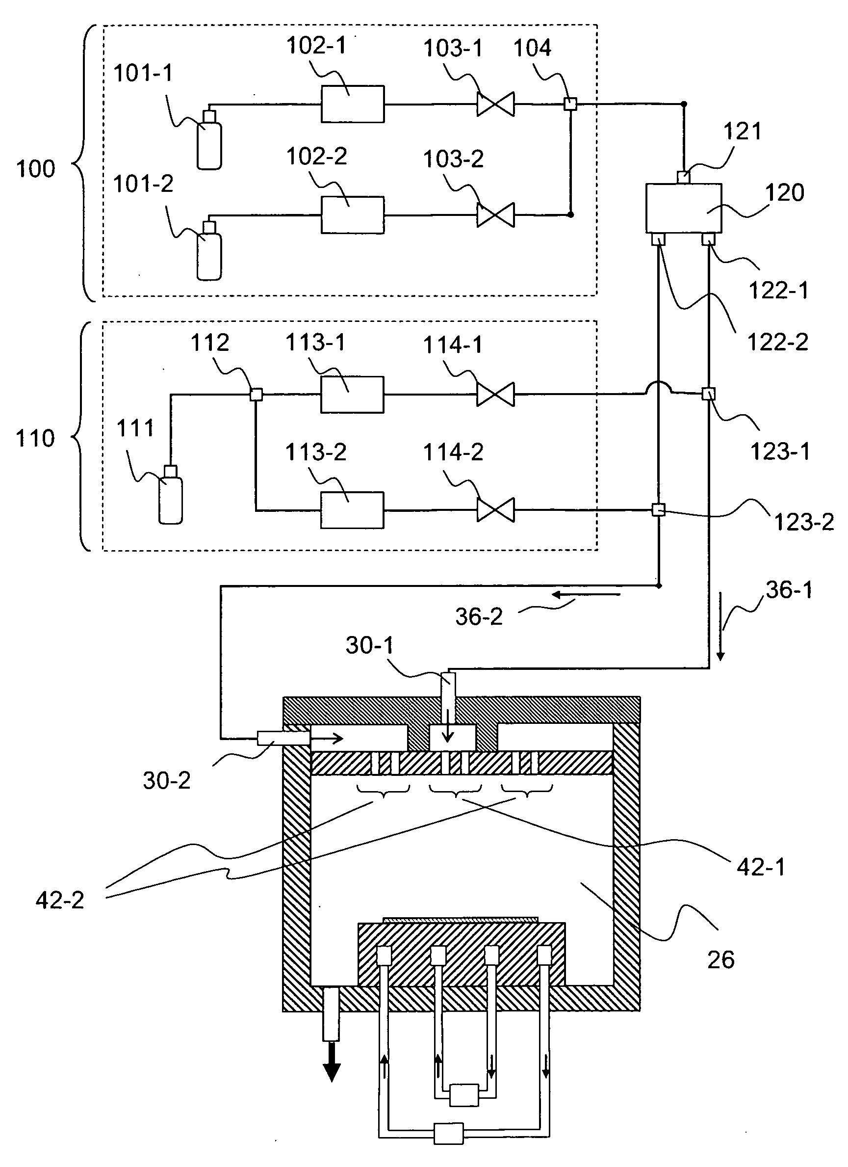
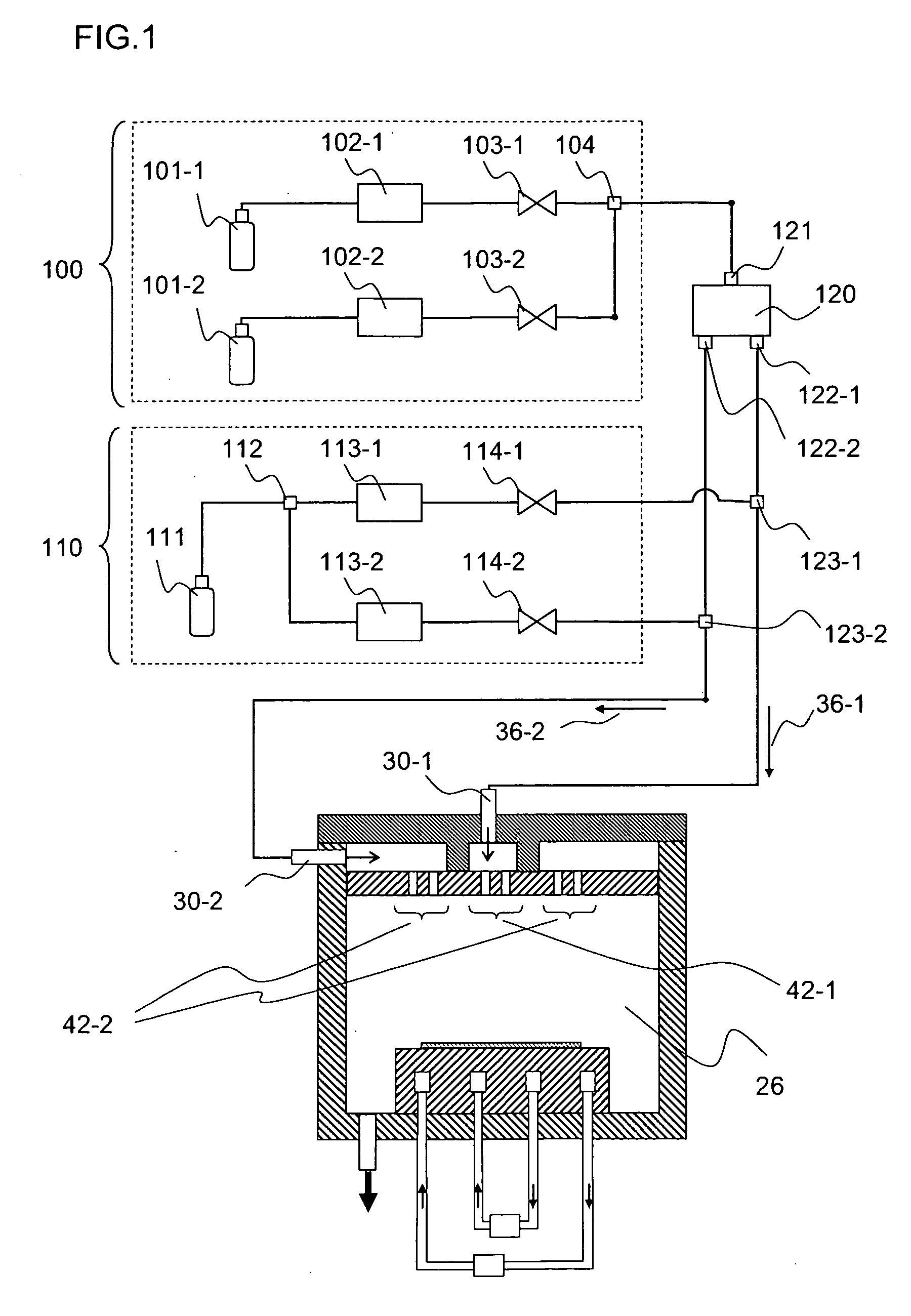
[0041]FIG. 1 is a schematic view of a UHF-ECR plasma etching apparatus and a gas system of the etching apparatus according to Embodiment 1 of the present invention. The gas system includes a common gas system 100 and an additive gas system 110. The common gas system 100 includes gas supply units 101-1 and 101-2, which serve as gas supply sources, flow controllers 102-1 and 102-2 for controlling the flow rates of respective gases, valves 103-1 and 103-2 for controlling respective gas flows, and a confluence 104 where the gases in the common gas system 100 join into one. In the present embodiment, the gas supply unit 101-1 contains hydrogen bromide (HBr) and the gas supply unit 101-2 contains chlorine (Cl2) as common gases.

[0042] The mixed common gas in the confluence 104 enters a downstream gas flow divider 120. The gas flow divider 120 divides a gas flowing through an inlet 121 into a plurality of (two in the present embodiment) gases flowing through outlets 122-1 and 122-2 at any ...

embodiment 2

[0075] An etching step 1 is the etching step of the antireflection coating 5, that is, a BARC etching step. The temperatures of the inner portion and the outer portion of the specimen 1 are adjusted to desired temperatures to achieve the target CD shift in the BARC etching step. For example, in the present embodiment, the desired temperatures are 16° C. at the center portion and 10° C. at the outer portion. The specimen 1 is heated by plasma 38 during etching. As described above, heat is transferred from the specimen 1 to the specimen holder 28 via a helium gas flowing between the specimen 1 and the specimen holder 28 to control the temperature of the specimen 1. In this case, the temperature of a refrigerant circulating in the specimen holder 28 must be lower than the temperature of the specimen 1. In the BARC etching step, to achieve the desired temperatures at the center portion and the outer portion of the specimen 1, the temperatures of the inner circulator 64-1 and the outer c...

embodiment 3

[0080] Embodiment 3 of the present invention is described below with reference to FIG. 6. In the present embodiment, the structures and the control techniques described in Embodiments 1 and 2 are applied to a gate etching process including a plurality of steps of a BARC etching step and a polysilicon etching step but not including a nonoperating step.

[0081]FIG. 6A illustrates the temperatures at the center portion and the outer portion of the specimen 1. The temperature 80 at the center portion is indicated by a solid line. The temperature 82 at the outer portion is indicated by a broken line. FIG. 6B illustrates the flow rates of oxygen in the first processing gas 36-1 and the second processing gas 36-2. The oxygen flow rate 84 in the first processing gas 36-1 is indicated by a solid line. The oxygen flow rate 86 in the second processing gas 36-2 is indicated by a broken line. FIG. 6C illustrates the flow rates of chlorine flowing through the central gas inlet region 42-1 and the ...


PUM

PropertyMeasurementUnit
internal pressureaaaaaaaaaa
temperatureaaaaaaaaaa

Abstract

A plasma etching apparatus includes a processing chamber in which a specimen is subjected to plasma processing, a specimen holder for holding the specimen, the specimen holder including a temperature controller for controlling temperatures at at least 2 positions of the specimen, at least two gas supply sources for supplying processing gases, at least two gas inlets for introducing the processing gases into the processing chamber, a regulator for independently controlling the compositions or the flow rates of the processing gases introduced from the at least two gas inlets and the temperatures controlled with at least two temperature controllers in the specimen holder, and an electromagnetic wave supply unit for sending an electromagnetic wave into the processing chamber, wherein the compositions or the flow rates of the processing gases introduced from the gas inlets and the temperature controlled with the temperature controllers in the specimen holder are independently controlled.

Description

[0001] The present application is based on and claims priority of Japanese patent application No. 2005-268316 filed on Sep. 15, 2005, the entire contents of which are hereby incorporated by reference. BACKGROUND OF THE INVENTION [0002] 1. Field of the Invention [0003] The present invention relates to a plasma etching apparatus for processing a semiconductor substrate, such as a semiconductor wafer, and to a plasma etching method using the plasma etching apparatus. [0004] 2. Description of the Related Art [0005] Conventionally, a plasma etching apparatus utilizing reactive plasma has been used to process a semiconductor substrate, such as a semiconductor wafer, in a manufacturing process of a semiconductor device. [0006] As an example of the plasma etching, etching for forming a polysilicon (poly-Si) gate electrode of a metal oxide semiconductor (MOS) transistor (hereinafter referred to as gate etching) is described below with reference to FIGS. 7A to 7C. As illustrated in FIG. 7A, a...

Claims


Application Information

Patent Timeline
Patent Type & Authority Applications(United States)
IPC IPC(8): C23F1/00G01L21/30H01L21/306H01L21/302G01R31/00
CPCH01J37/32449H01J37/32935H01L21/67253H01L21/67069H01L21/67248H01L21/32137
Inventor MIYA, GOKANNO, SEIICHIROITABASHI, NAOSHIYOSHIGAI, MOTOHIKOTANAKA, JUNICHIMORI, MASAHITOKOFUJI, NAOYUKISAITO, GO
Owner HITACHI HIGH-TECH CORP
Features
  • Generate Ideas
  • Intellectual Property
  • Life Sciences
  • Materials
  • Tech Scout
  • Unparalleled Data Quality
  • Higher Quality Content
  • 60% Fewer Hallucinations
Learn More