Method of manufacturing ink jet recording head

a manufacturing method and technology of applied in the field of manufacturing ink jet recording head, can solve the problems of loss of reproducibility of oh distance for each uneven oh distance at the peripheral edge of the respective ones of the discharge ports, and dispersed discharge volume and discharge direction among the discharge ports, so as to achieve the effect of increasing the density of the ink passage pattern

Inactive Publication Date: 2007-03-15
CANON KK
View PDF19 Cites 12 Cited by
  • Summary
  • Abstract
  • Description
  • Claims
  • Application Information

AI Technical Summary

Benefits of technology

[0010] Accordingly, one object of the present invention is to provide a method capable of precisely manufacturing an ink recording head even though the density of the ink passage pattern is increased.
[0014] (2) depositing an organic material on the substrate which has been formed thereon with the ink passage pattern with the dissoluble resin by a vapor growth process at a temperature at which the dissolubility of the dissoluble resin is not lost, in order to form a coated resin layer;
[0017] According to the present invention, the ink jet recording head can be manufactured with a high degree of accuracy even though the density of the ink passage pattern is increased.

Problems solved by technology

As a result, the reproducibility of the OH distance for each of the discharge ports is lost, and as well the OH distance at the peripheral edge of the respective ones of the discharge ports becomes uneven, depending upon a position.
Thus, there has been offered such a risk that the discharge volume and a discharge direction are dispersed among the discharge ports or the recording heads.

Method used


Image

  • Method of manufacturing ink jet recording head
  • Method of manufacturing ink jet recording head
  • Method of manufacturing ink jet recording head

Examples


embodiment 1

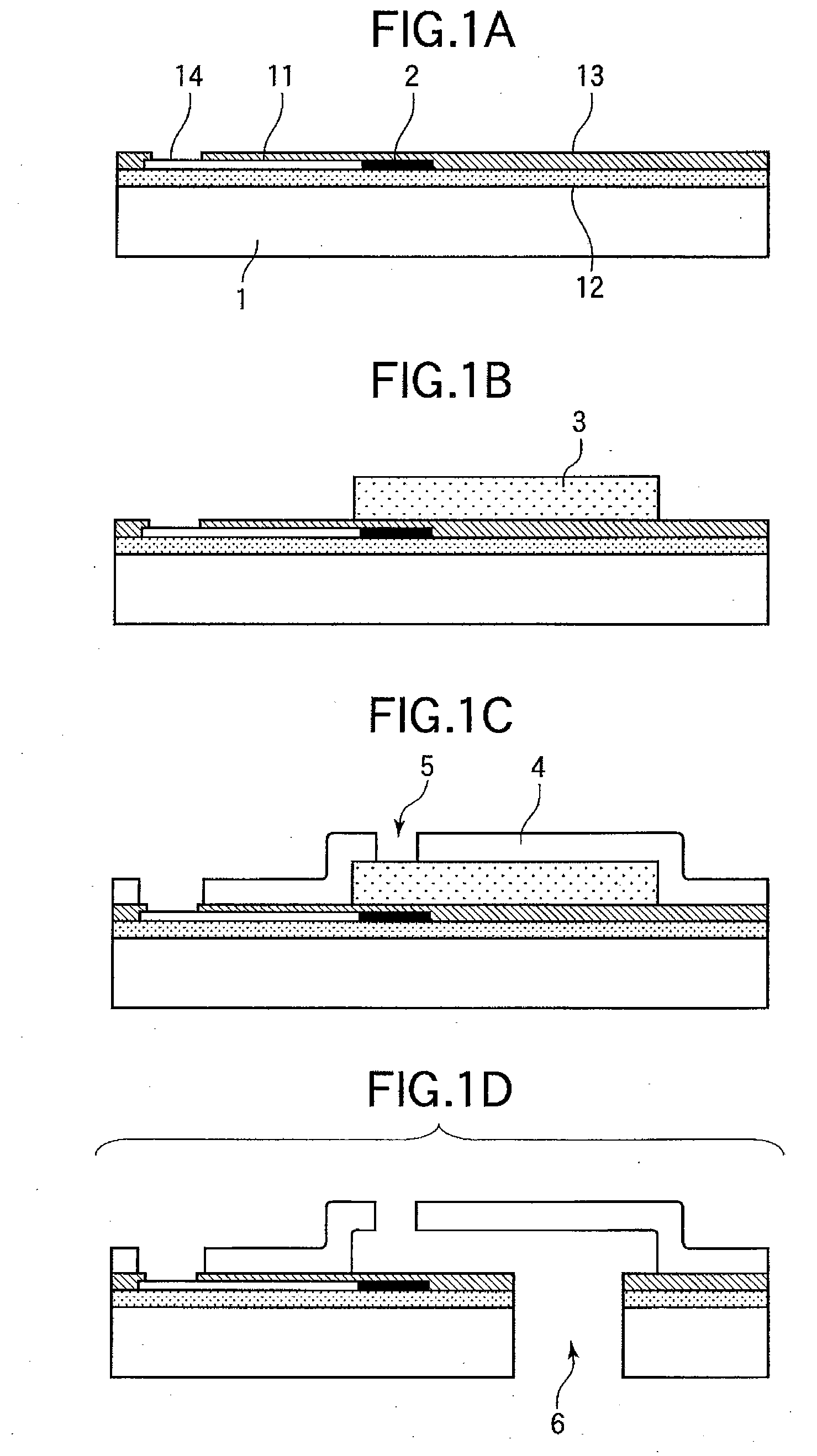
[0055] At first, electrothermal transducer elements (heat generating resistors made of TaN) as discharge pressure elements, a drive circuit therefor, and an etching stop layer formed from a silicon oxide film were formed on a single crystal silicon substrate.

[0056] Next, polyamide resin was coated so as to form an adherence layer, and after baking, a novolac group photoresist was coated. After patterning of the novolac group photoresist with the use of photolithographic technology, the polyamide resin at least on the electrothermal transducer elements, on pads for external electrodes, and at the supply port forming position was removed by chemical dry etching with the use of CF4 and O2. Thereafter, the novolac group photoresist was removed by a monoamine group stripper.

[0057] Then, polymethylisopropenylketone as dissoluble resin was coated on the substrate by a spin coat process so as to form a dissoluble resin layer. After prebaking for 20 min. at a temperature of 120° C., patter...

embodiment 2

[0063] In this embodiment, polymethylmethaclyrate was selected as the dissoluble resin, and was then patterned so as to form an ink passage pattern by process steps similar to those in the embodiment 1.

[0064] Then, substrate was introduced in a vacuum chamber which has been evacuated up to about 10−3 Pa, and 4,4′-diphenylmethandiisocyanate (MDI) and 4,4′-methylenedianiline (MDA) were introduced by being heated up to temperatures of 71° C., 100° C., respectively, and sublimated. Polyurea resin was formed into a film by a deposition polymerization process. The novolac group photoresist was coated thereover. Then, with the use of a photomask having a certain pattern, pattern exposure for forming the ink discharge ports was carried out. Thereafter, it is dipped in an about 3 wt. % TMAH aqueous solution so as to be developed. Then, gas was introduced onto a parallel-plate type RIE for etching so as to form the ink discharge ports, and thereafter, the novolac group photoresist was remove...


PUM

PropertyMeasurementUnit
distanceaaaaaaaaaa
thicknessaaaaaaaaaa
temperatureaaaaaaaaaa

Abstract

Provided is a method capable of manufacturing an ink jet recording head with a high degree of accuracy even though the density of an ink passage pattern is increased. The method of manufacturing an ink jet recording head according to the present invention comprises the steps of forming an ink passage pattern on a substrate formed therein with ink discharge pressure generating elements from dissoluble resin; depositing an organic material on the substrate formed thereon with the ink passage pattern from the dissoluble resin by a vapor growth process at a temperature at which the dissolubility of the dissoluble resin is not lost, so as to form a coated resin layer; forming ink discharge ports in the coated resin layer in parts located above the ink discharge pressure generating elements; and eluting the dissoluble resin.

Description

BACKGROUND OF THE INVENTION [0001] 1. Field of the Invention [0002] The present invention relates to a method of manufacturing an ink jet recording head for discharging droplets. [0003] 2. Description of the Related Art [0004] An ink jet recording head used in an ink jet recording system (liquid jetting recording system) incorporates several microscopic recording liquid discharge ports, liquid passages and liquid discharge pressure generating portions which are formed in a part of the liquid passages. Further, in order to obtain a high quality image by this ink jet recording head, droplets of recording liquid (ink) are always discharged from the respective discharge ports, desirably by one and the same volume at an equal discharge speed. [0005] As a method which can satisfy the above-mentioned desire, the specification of U.S. Pat. No. 5,218,376 discloses a method in which air bubbles are formed in ink by generating thermal energy in ink discharge pressure generating elements (elect...

Claims


Application Information

Patent Timeline
Patent Type & Authority Applications(United States)
IPC IPC(8): B41J2/05
CPCB41J2/1603B41J2/1628B41J2/1629B41J2/1631B41J2/1632Y10T29/49083B41J2/1639B41J2/1642B41J2/1645Y10T29/49401Y10T29/42B41J2/1635
Inventor HAYAKAWA, KAZUHIRO
Owner CANON KK
Why Eureka
Try Eureka