Fluid interface for bioprocessor systems

a bioprocessor and interface technology, applied in the field of fluid interface for bioprocessor systems, can solve the problems of affecting the growth of process bacteria, difficult macromolecule analysis in complex mixtures, and numerous problems in the sampling of an operating bioreactor, so as to facilitate rapid, frequent, automated sampling, and improve the effect of sampling accuracy and frequency

Inactive Publication Date: 2007-03-29
GROTON BIOSYST
View PDF33 Cites 35 Cited by
  • Summary
  • Abstract
  • Description
  • Claims
  • Application Information

AI Technical Summary

Benefits of technology

[0016] The methods and apparatus disclosed herein provide significant advantages to aseptically sampling a biofluid and directing it to a bioprocess site. The valve and conduit system excludes environmental contamination and facilitates rapid, frequent, automated sampling. The trap allows the use of simple valves yet avoids the problems associated with valve deadspace. Furthermore, the trap provides the ability to detect flow, e.g. from a failing valve, before backflow or cross-contamination occurs. Additionally, the valved, automated system coupled to a wash fluid source and a waste site allows the system to be thoroughly cleaned between sample cycles, thus assuring contamination-free sampling. The result is improved sampling accuracy and frequency for improved control and lower cost in bioprocess systems.

Problems solved by technology

Analysis of macromolecules in complex mixtures is challenging in many chemical and biochemical processes.
Effective process control generally requires accurate and frequent sampling, yet sampling of an operating bioreactor is associated with numerous problems, particularly contamination from sampling.
Other contaminants, e.g., chemical contaminants, can affect the growth of the process bacteria and can confound the analysis of process components in the bioreactor fluid.
Contamination can also affect the sampling and analysis apparatus.
For example, wild or process bacteria can colonize the sampling / analysis system, or the system can accumulate other components form the biofluid, e.g., as salts, nutrients, proteins, peptides, cells, cell components, biopolymers such as polysaccharides, all of which can confound analysis of the desired products.
Additionally, frequent sampling can lead to build-up of the molecule or molecules being analyzed, which can lead to inaccuracy.
In particular, the problem of “backflow”, i.e., liquid cross-contamination, is especially difficult when interfacing two fluidic systems.
Simple valve interfaces are inadequate because valves typically have crevices, joints, dead volume, and the like, where contaminants can lodge and accumulate, only to be released during another sample cycle.
Additionally, valves can fail and allow undesirable contamination to occur before much measurable fluid has leaked.
More complex valved interfaces are known, but some are costly and still suffer some of the problems of simple valve systems, while other examples are unsuitable for high pressure systems.
Needle / septa interfaces are known to avoid backflow but have issues with septa lifetime, needle contamination during transfer, and are particularly troublesome for frequent, automated sampling of larger volumes.
Furthermore, septa replacement itself opens the system for contamination.
Matrix chromatography uses expensive columns that can be prone to plugging when used with complex mixtures that include insoluble or precipitation-prone components.
Centrifugation can be effective but can cause contamination problems as there is no way to readily isolate a sample from the environment during the various sample transfers typically employed, and the size of the centrifuge limits the amount of macromolecule that can be prepared at one time.
Thus both methods are low throughput in terms of amount of macromolecule that can be prepared.
Additionally, both methods are low throughput in terms of the sampling frequency, as the time from sample extraction from a complex bioreactor mixture to analysis of the macromolecule can easily be four hours or more.
Such a slow analysis time leads to poor optimization of reactor processes, resulting in lowered yields, increased costs, increased purification demands, and increased amounts of potentially hazardous biological waste. FIG. 3 depicts a hypothetical example comparing two sampling frequencies, wherein a lower sampling frequency versus time (squares) can miss details in the level of a desired macromolecule versus time (solid line) in a reaction mixture, compared to a higher sampling frequency (circles).
Furthermore, small capillaries are physically fragile and are not suited to high-throughput separations, being easily plugged from the many macromolecules and debris in a complex mixture.
In particular, rapid separation and analysis of macromolecules from complex liquid mixtures, for example, during the analysis of proteins produced in a bioreactor, is especially challenging.
The repetitive motion can easily break the CE column.
In either case, column replacement requires time-consuming recalibration of the robotic motion.
While this hardware is durable, the separation efficiency is limited by the length of CE channel that can be fabricated on a chip.
Attempts to extend the channel length by increasing channel density on a chip generally restrict high electric fields from use, increasing separation time.
Also, the throughput of this technique is limited.
Furthermore, sample transfer as practiced in both the robotic capillary technique and the chip technique expose the analytic solution to undesirable environmental contamination.

Method used


Image

  • Fluid interface for bioprocessor systems
  • Fluid interface for bioprocessor systems
  • Fluid interface for bioprocessor systems

Examples


Embodiment Construction

[0044] A description of preferred embodiments of the invention follows.

[0045] The methods and apparatus disclosed herein are generally related to analyzing a sample of a molecular analyte, e.g., a macromolecule, from a complex liquid mixture. The invention has particular application to automated methods and apparatus for capillary electrophoretic analysis macromolecules, e.g., proteins, from a complex bioreactor liquid mixture.

Automated Macromolecule Preparation

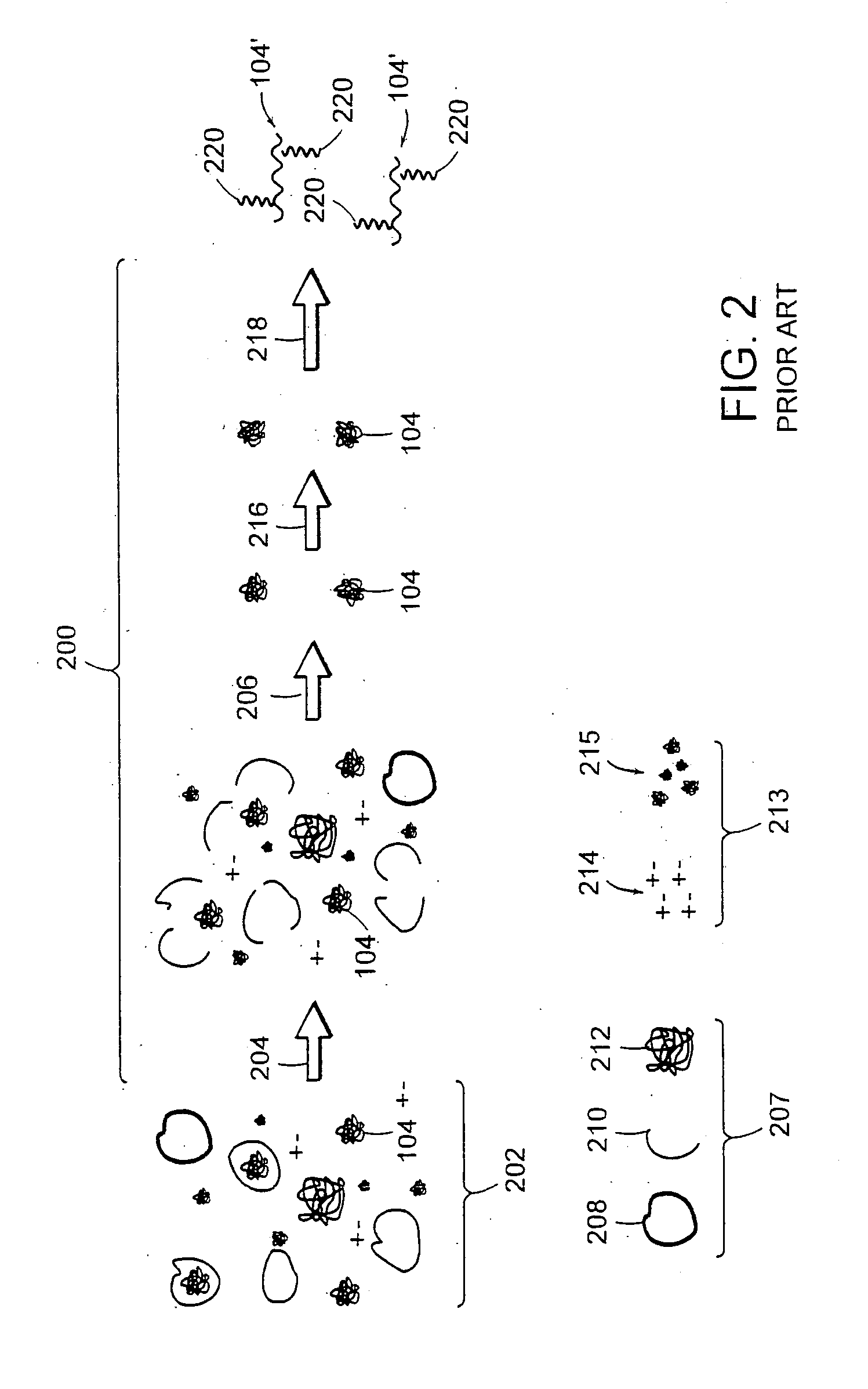
[0046]FIG. 4 depicts a schematic of steps that can be included in preparing a macromolecule sample. The liquid, typically aqueous, mixture 202 contains the macromolecule 104, and can also contain fine components 213, e.g., salts, molecules smaller than the macromolecule, and the like; and rough components 207, e.g., cells, cell fragments, particulate contaminants, molecules larger than the macromolecule, and the like.

[0047] Macromolecule 104 can be dissolved in the liquid mixture, or can be partially contained in cells, ...


PUM

PropertyMeasurementUnit
diameteraaaaaaaaaa
timeaaaaaaaaaa
diameteraaaaaaaaaa

Abstract

An apparatus and method for an aseptic fluidic interface between bioprocess systems is provided. The apparatus includes an inlet valve, adapted for automatic control, that is coupled to a biofluid source site. A sampling conduit extends from the inlet valve to an outlet valve. The outlet valve is adapted for automatic control and is coupled to a biofluid process site. A trap is at the sampling conduit. A waste valve, adapted for automatic control, is located at a waste conduit extending from the sampling conduit to a waste site. Also included is a wash fluid source that is coupled to at least one of the inlet or outlet valves. In the method, the sample is automatically directed to the biofluid process site by opening the outlet valve, and closing the waste valve Also included is isolating the biofluid sites by closing the inlet and outlet valves, and opening the waste valve to drain biofluid from the trap to the waste site. Another step is cleaning the sampling conduit before sample collection by directing the wash fluid through at least one valve selected from the inlet and outlet valves, and subsequently through the waste valve to the waste site.

Description

RELATED APPLICATION [0001] This application is a divisional of U.S. application Ser. No. 10 / 601,083, filed Jun. 20, 2003. The entire teachings of the above application are incorporated herein by reference.BACKGROUND OF THE INVENTION [0002] Analysis of macromolecules in complex mixtures is challenging in many chemical and biochemical processes. For example, the analysis of a macromolecule product, e.g., a protein, typically involves first preparing a sample of a macromolecule from a complex mixture for analysis. FIG. 1 depicts an example of a macromolecule preparation process 100, which involves taking a sample from a complex liquid mixture, e.g. a biofluid in a bioreactor 102, separating a macromolecule 104 from other components in the mixture, and processing it to deliver a prepared macromolecule 104′ for analysis at analyzer 106. [0003] Effective process control generally requires accurate and frequent sampling, yet sampling of an operating bioreactor is associated with numerous p...

Claims


Application Information

Patent Timeline
Patent Type & Authority Applications(United States)
IPC IPC(8): C12M1/26C12M1/36B01D61/14B01D61/16B01D61/18G01N1/00G01N1/20
CPCB01D61/142B01D61/16B01D61/18B01D2311/04G01N1/2035G01N35/1097G01N27/44704B01D2311/12B01D2311/16Y10T137/4259Y10T137/4266B01D61/146
Inventor BARRINGER, GEORGE E. JR.
Owner GROTON BIOSYST
Why Eureka
Try Eureka