Method and device for high-capacity entrained flow gasifier

a gasifier and high-capacity technology, applied in the direction of gasifier mechanical details, combustible gas production, combustible gas purification/modification, etc., can solve the problems of high repair cost, rapid wear, and increase in wear process with increasing ash content, so as to achieve reliable and safe operation

Inactive Publication Date: 2007-04-12
SIEMENS AG
View PDF6 Cites 101 Cited by
  • Summary
  • Abstract
  • Description
  • Claims
  • Application Information

AI Technical Summary

Benefits of technology

[0011] It is therefore an object of this invention to provide a gasification method that permits maximum capacities of 1,000 to 1,500 MW with reliable and safe operation.

Problems solved by technology

This has the drawback that the refractory masonry is loosened by the liquid slag formed during gasification, which leads to rapid wear and high repair costs.
This wear process increases with increasing ash content.
Thus, such gasification systems have a limited service life before replacing the lining.
Also, the gasification temperature and the ash content of the fuel are limited; see C. Higman and M. van der Burgt, “Gasification”, Verlag ELSEVIER, USA, 2003.
This joint discharge of gasification gas and slag can lead to plugging of the conduit and thus to limitation of availability.
However, because of entrained liquid slag particles, there is the danger of deposition and coating of heat exchanger surfaces, which hinders heat transfer and may lead to plugging of the pipe system and / or erosion.
A series of drawbacks detract from the advantage of waste heat recovery by this system.
Deposits form on the heat exchanger tubes, which lead to hindrance of heat transfer and to corrosion and erosion, and thus to lack of availability.
This central discharge in the central pipe is susceptible to plugging that interferes with the overall operation, and reduces the availability of the entire system.
The capacity of the various gasification technologies mentioned is limited to about 500 MW, which is attributable in particular to the fuel infeed to the gasification reactor.

Method used


Image

  • Method and device for high-capacity entrained flow gasifier
  • Method and device for high-capacity entrained flow gasifier
  • Method and device for high-capacity entrained flow gasifier

Examples


Embodiment Construction

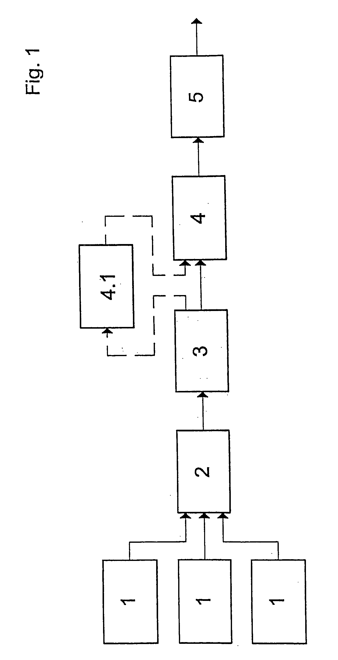
[0024]FIG. 1 shows a block diagram of the process steps of pneumatic metering of pulverized fuel, gasification in a gasification reactor with cooled reaction chamber structure 2, quench-cooling 3, crude gas scrubbing 4, in which there can be a waste heat boiler 4.1 between the quench-cooling 3 and the crude gas scrubbing 4, and a condensation or partial condensation 5 follows the crude gas scrubber 4.

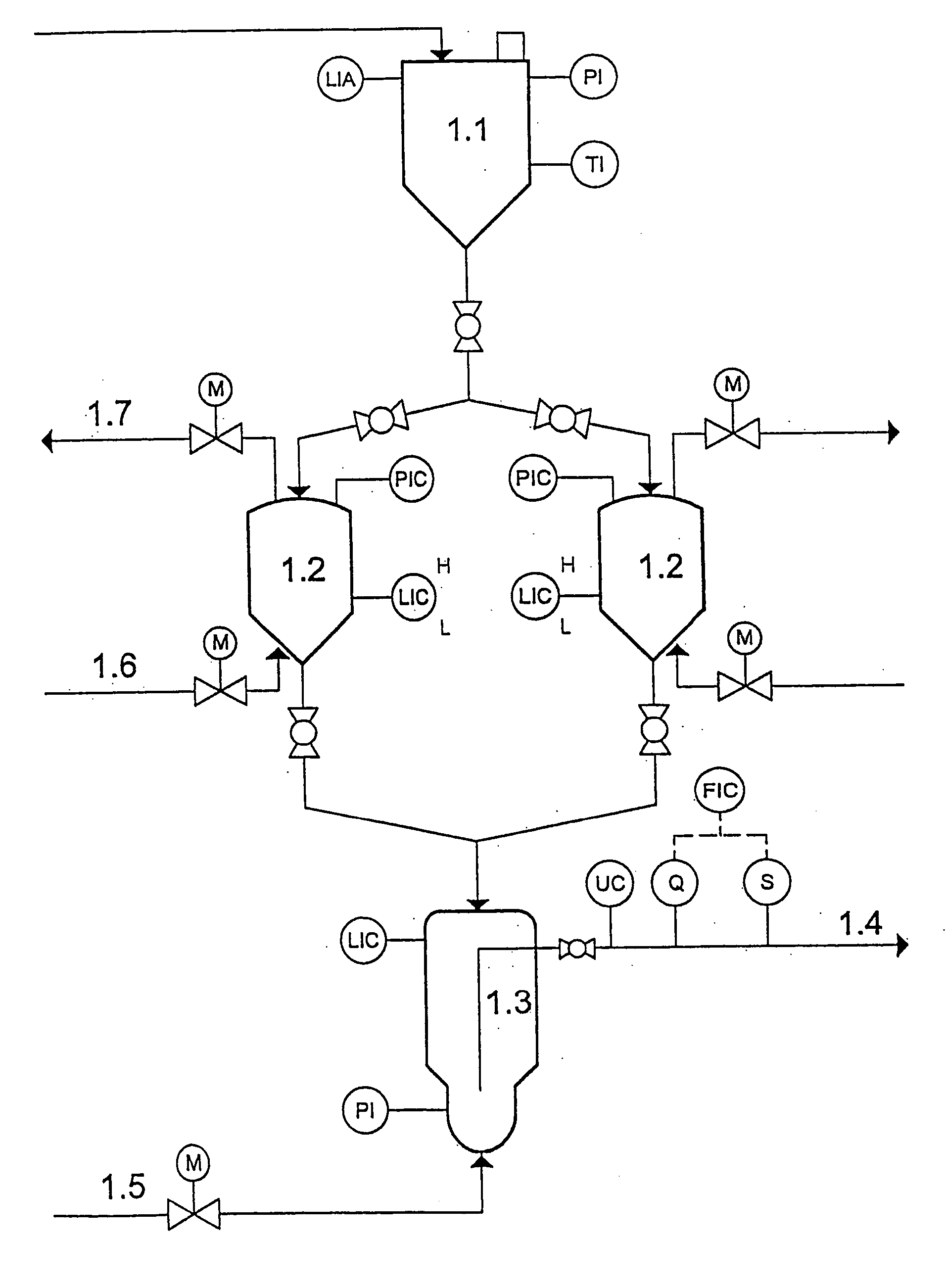
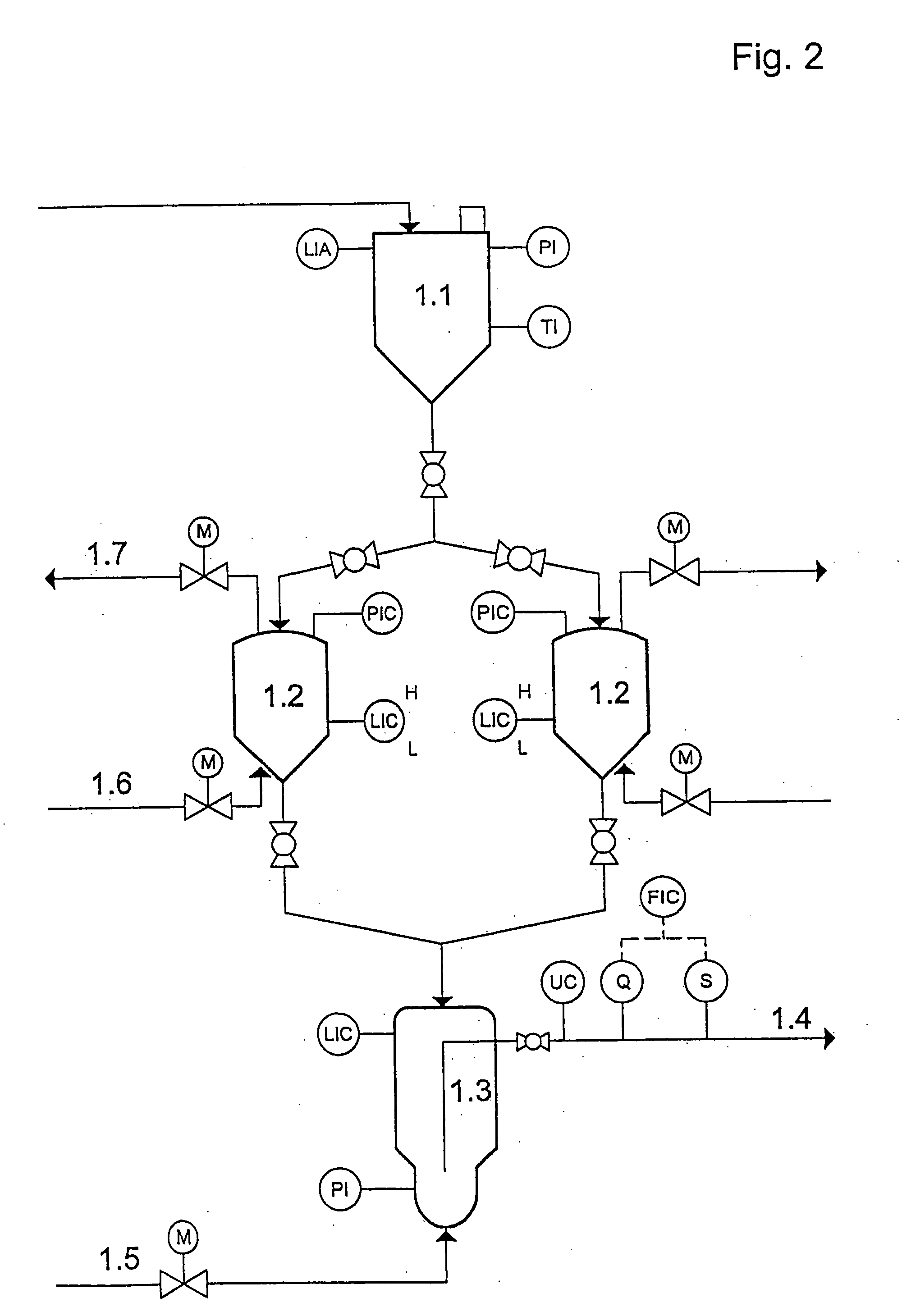
[0025]FIG. 2 shows a metering system for pulverized fuel consisting of a bunker 1.1 followed by two pressurized sluices 1.2, into which lead lines 1.6 for inert gas, and at the top of which depressurization lines 1.7 exit, with lines to the metering tank 1.3 leaving the pressurized sluices 1.2 from the bottom. There are fittings on the pressurized sluices 1.2 for monitoring and regulating. A line 1.5 for fluidizing gas leads into the metering tank from below, which provides for fluidizing the gas, and the fluidized pulverized fuel is fed through the transport line 1.4 to a gasification...


PUM

PropertyMeasurementUnit
grain sizeaaaaaaaaaa
pressureaaaaaaaaaa
temperaturesaaaaaaaaaa

Abstract

A method and device for the gasification of pulverized fuels from solid fuels such as bituminous coals, lignite coals, and their cokes, petroleum cokes, coke from peat or biomass, in entrained flow, with an oxidizing medium containing free oxygen, by partial oxidation at pressures between atmospheric pressure and 80 bar, and at temperatures between 1,200 and 1,900° C., at high reactor capacities between 1,000 and 1,500 MW. The method uses the following steps: metering of the fuel, gasification reaction in a gasification reactor with cooled reaction chamber contour, quench-cooling, crude gas scrubbing, and partial condensation.

Description

BACKGROUND OF THE INVENTION [0001] 1. Field of the Invention [0002] The invention relates to a method for entrained flow gasification with very high capacity that can be used for supplying large-scale syntheses with synthesis gas. The invention enables the conversion of fuels refined into pulverized fuel, such as lignite and bituminous coals, petroleum coke, solid grindable refuse, and solid-liquid suspensions, so-called slurries, into synthesis gas. The fuel is reacted at temperatures between 1,200 and 1,900° C. with a gasification medium containing free oxygen, at pressures up to 80 bar, by partial oxidation to gases containing CO and H2. This is done in a gasification reactor that is distinguished by a multiple-burner system and by a cooled gasification chamber. [0003] 2. The Prior Art [0004] The autothermic entrained flow gasification of solid, liquid, and gaseous fuels has been known in the technology of gas production for years. The ratio of fuel to gasification medium contain...

Claims


Application Information

Patent Timeline
Patent Type & Authority Applications(United States)
IPC IPC(8): C10J3/00
CPCC10J3/466C10J3/506C10J3/84C10J3/845C10J2200/09C10J2200/156C10J2300/0916C10J2300/093C10J2300/0959C10J2300/1634C10J2300/1687C10K1/101Y02P20/129Y02P20/145
Inventor SCHINGNITZ, MANFREDMEHLHOSE, FRIEDEMANNLAMP, JOACHIMADLER, DIETMAR
Owner SIEMENS AG
Why Eureka
Try Eureka