Cytometer

a cytometer and cytometer technology, applied in the field of cytometers, can solve the problems of large amount of unconditioned analog data, large equipment and high input-output (i/o) bonding pad count, etc., to achieve the effect of reducing costs, facilitating portability, and enhancing device reliability

Inactive Publication Date: 2007-04-19
UTI LLP
View PDF4 Cites 49 Cited by
  • Summary
  • Abstract
  • Description
  • Claims
  • Application Information

AI Technical Summary

Benefits of technology

[0007] In accordance with a further embodiment of the invention, the cytometer may futhermore provide the necessary feedback to function as a closed loop optical control system. Combination of onboard digital signal processing in a microfluidic chip eliminates the need for fiber optics cables, photomultiplier collection, analog to digital conversion and conventional microscopy for it's operation. Onboard digital processing ensures that the system can be readily miniaturized for portability as compared to more conventional cytometry systems. The approach also addresses issues of μTAS manufacturability, affordability and repeatability. Multi-chip-module (MCM) based hybrid integration and advanced packaging technologies stand to reduce costs and enhance reliability of devices in the μTAS or fluidic microsystems domain. The cytometer may also provide disposable utility in applications that cannot tolorate sample cross contamination. To enhance such disposability, the digital processor may be designed as a custom CMOS integrated circuit. Furthermore, microfluidic assembly technologies can further ensure system cost and function can meet the stringent demands of biological and medical devices.

Problems solved by technology

While commonplace in larger microbiology centers, FACS machines are large and expensive pieces of equipment which typically require highly trained personnel for succesful, utility, including operation and maintenance.
The second device consists of a 2×20 photodiode array which, although capable of improved resolution, is plagued by a high input-output (I / O) bonding pad count and is furthermore challenged by the vast amounts of unconditioned analog data, that must be processed off chip in real time to demonstrate practicle utility.
However, these devices tend to be complex, with complex off chip processing.

Method used


Image

  • Cytometer
  • Cytometer
  • Cytometer

Examples


Embodiment Construction

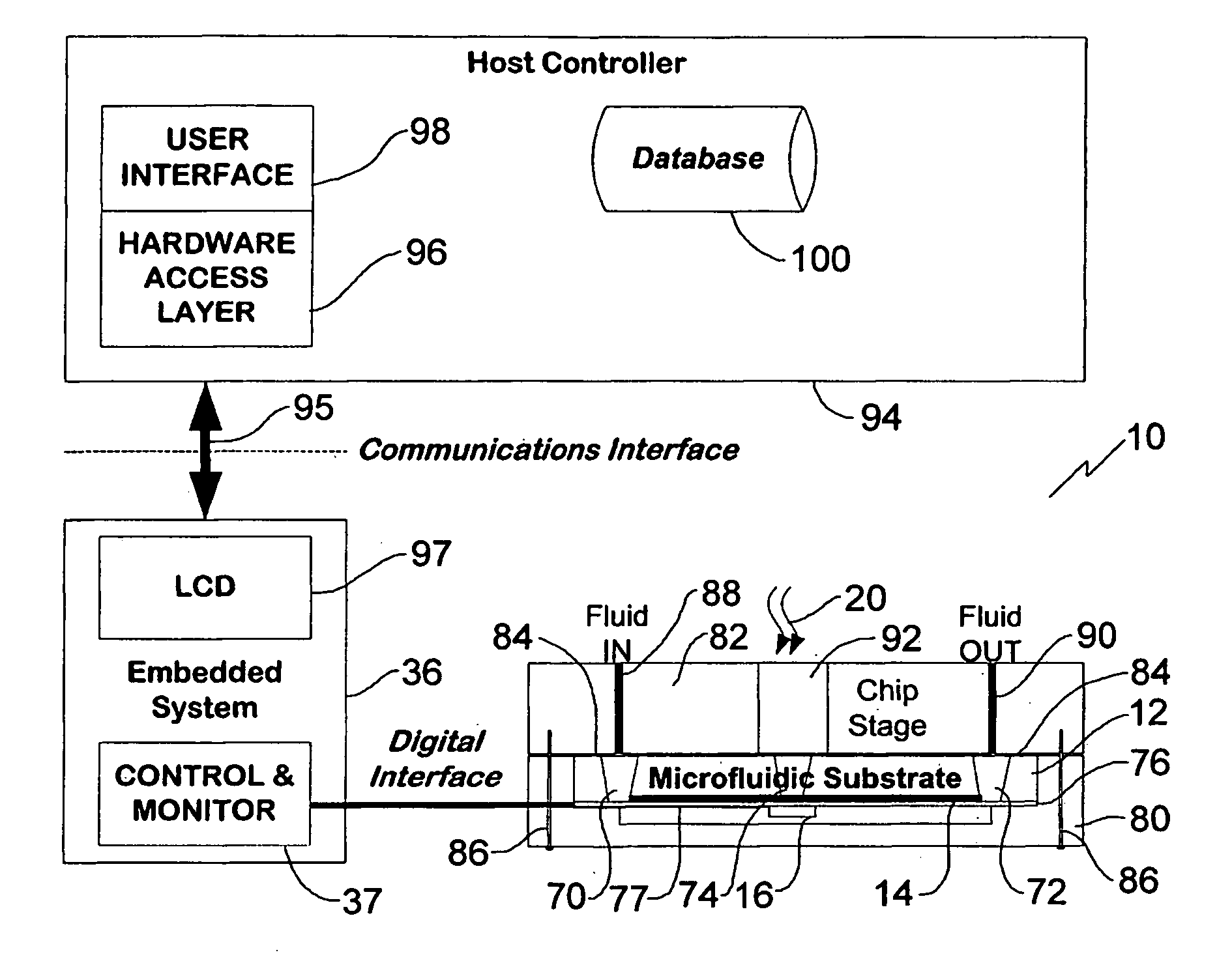
[0020] In the claims, the word “comprising” is used in its inclusive sense and does not exclude other elements being present. The indefinite article “a” before a claim feature does not exclude more than one of the feature being present. A cytometer is a device for counting a flow of particles, for example particles moving in or transported by a stream of fluid. The particles may be any particles, and may be microscopic particles such as cells or may be individual liquid droplets. The particles may also be macroscopic objects such as vehicles. Electrical connections between block components are represented by lines in the drawings, but will be understood to represent conventional connectors available from electronics manufacturers, or patterned chip electrical connections formed in a conventional manner.

[0021] A schematic diagram of a digital cytometer 10 is illustrated in FIG. 1. The cytometer 10 comprises a muli-layered microfluidic chip. In the several layers of the cytometer 10 ...


PUM

PropertyMeasurementUnit
widthaaaaaaaaaa
widthaaaaaaaaaa
Heightaaaaaaaaaa

Abstract

A real-time digital cytometer on a chip system utilizing a custom near field CMOS active pixel intelligent sensor that is flip-chip attached to a fluidic microchannel etched in a thin glass substrate. The CMOS active pixel sensor, fabricated using a 0.18 micron process, is a mixed signal chip comprising a sixteen pixel linear adaptive spatial filter coupled to a digital serial interface. This near field hybrid digital sensor topology obviates the need for both high resolution analog to digital conversion as well as conventional microscopy for the realization of real time optical cytometry. The custom sensor based design approach affords efficient scaling into a tiled multi-channel sensing configuration. The complete system, supported by a handheld graphical user interface and control module, demonstrates a viable micro total analysis sub-system for sample preparation and analysis which can support a wide range of applications ranging from cytometry to cell growth kinetics and analysis and various forms of fluid and droplet metering on an integrated and compact microfluidic platform.

Description

CROSS REFERENCE TO RELATED APPLICATIONS [0001] This application claims the benefit under 35 USC 119(e) of provisional patent application No. 60 / 667,117 filed Apr. 1, 2005, the content of which is incorporated by reference herein.BACKGROUND OF THE INVENTION [0002] A cytometer is a device that is employed to examine, count and subsequently sort microscopic sized particles, such as intact biological cells. In flow cytometry, such single particles, suitably tagged with fluorescence markers and immersed in an aqueous media are hydrodynamically focused by the sheath flow and made to traverse a small region of space illuminated by a focused laser beam. Depending on the optical characteristics of the cell traversing the focused coherent beam, and the chemo-optic markers it carries, the incident laser light will be scattered (forward scatter and backscatter) and / or induce floresence of the chemo-optic markers generated lightof different frequency. One or more of the optical signals emitted f...

Claims


Application Information

Patent Timeline
Patent Type & Authority Applications(United States)
IPC IPC(8): G01N33/00
CPCG01N15/1459G01N15/1484
Inventor HARTLEY, LEE F.YADID-PECHT, ORLYKALER, KARAN V.I.S.
Owner UTI LLP
Why Eureka
Try Eureka