Optically controlled optical-path-switching apparatus, and method of switching optical paths
a technology of optical path switching and optical signal transmission apparatus, which is applied in the direction of optical elements, instruments, lenses, etc., can solve the problems of insufficient development of switches for practical use, low response speed of types of apparatus, and intrinsic problem of heat diffusion, etc., to achieve no dependence, high speed, and high durability
- Summary
- Abstract
- Description
- Claims
- Application Information
AI Technical Summary
Benefits of technology
Problems solved by technology
Method used
Image
Examples
example 1
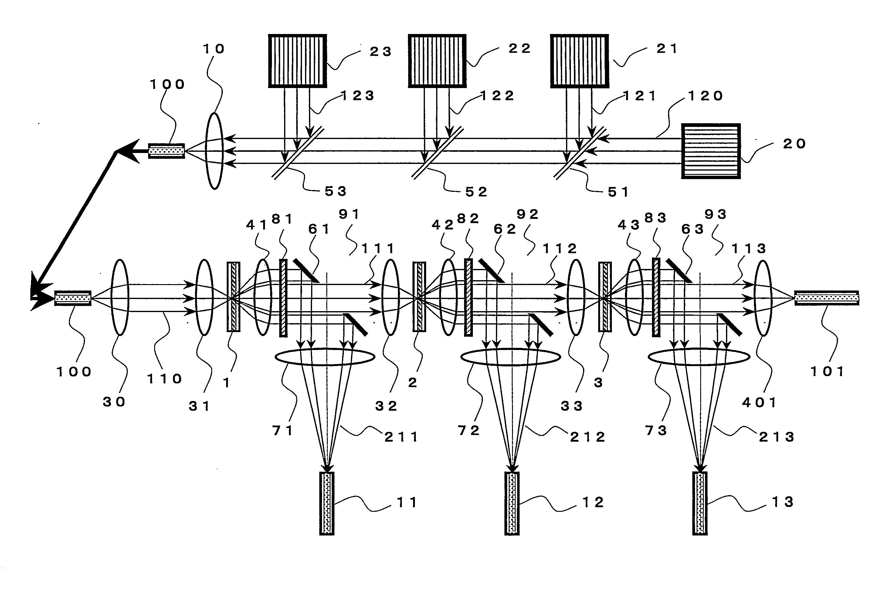
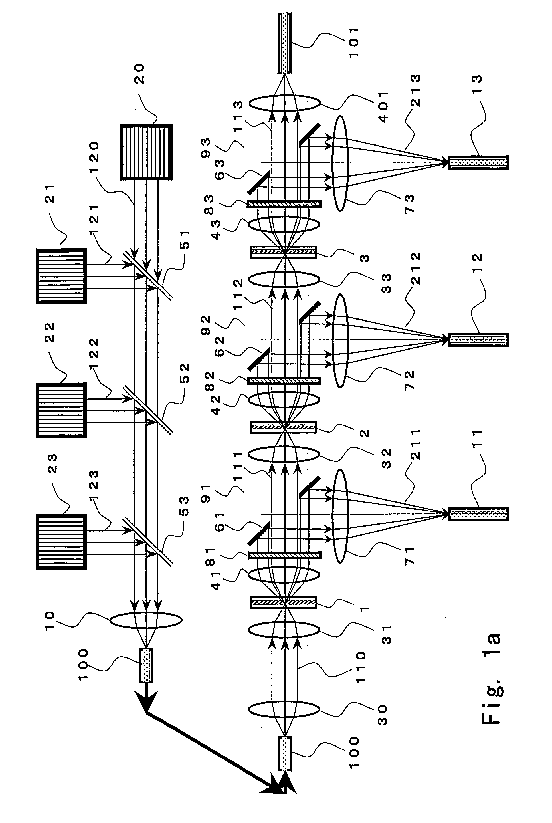
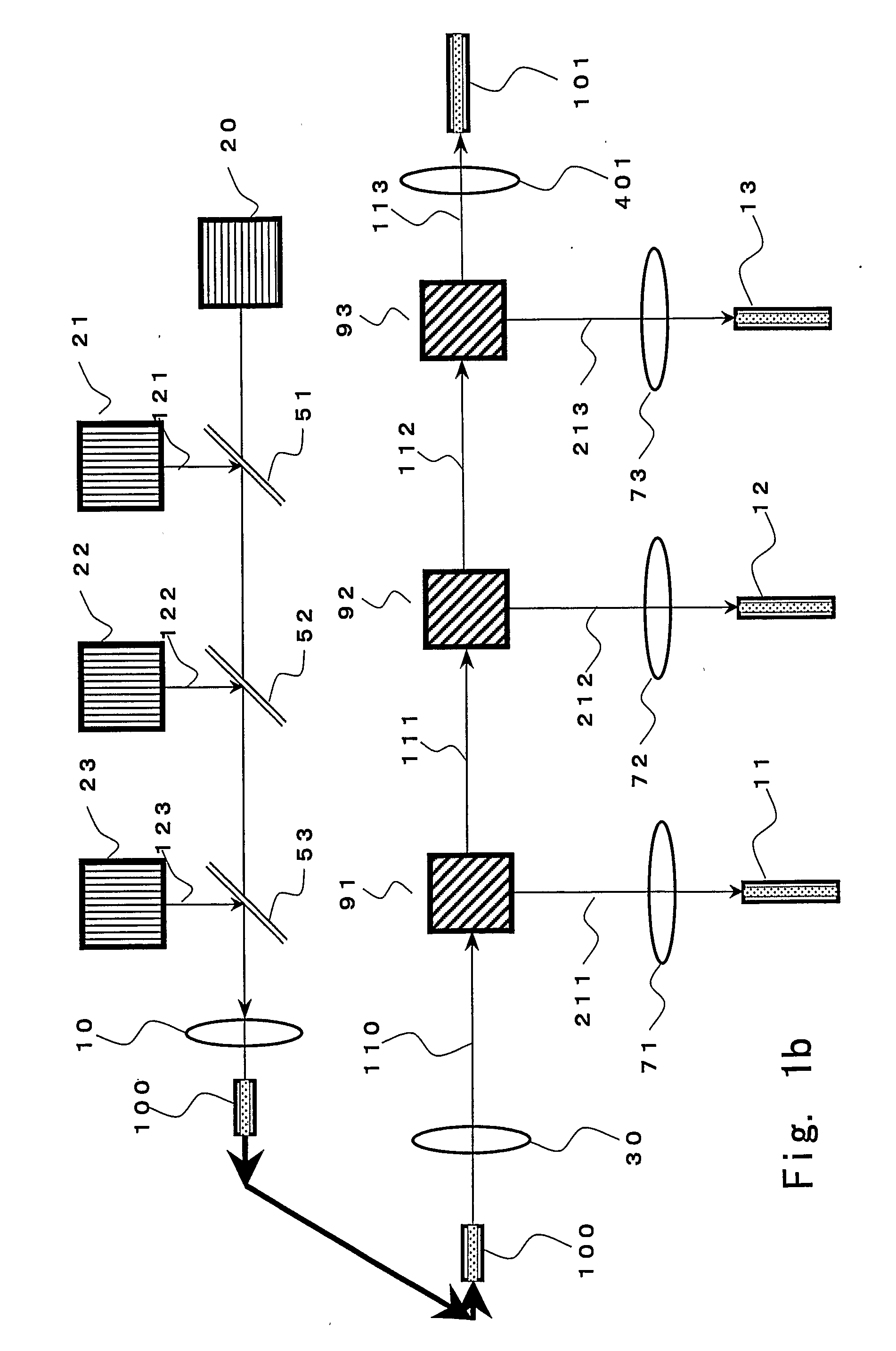
[0162] A schematic view of the configuration of an optically controlled optical-path-switching-type optical signal transmitting apparatus of Example 1 is shown in FIG. 1a. The optically controlled optical-path-switching-type optical signal transmitting apparatus of FIG. 1a exemplifies one (1) light source 20 for a signal light beam; three (3) light sources 21, 22, and 23 for control light beams having wavelengths that differ from each other and from the wavelength of the signal light beam 120; dichroic mirrors 51, 52, and 53 for aligning all the optical axes of and causing the signal light beam 120 and three (3) control light beams 121, 122, and 123 to propagate coaxially in the same direction; a condenser lens 10 for combining and causing the signal light beam 120 and the three (3) control light beams 121, 122, and 123 to enter an optic fiber 100; the optical fiber 100 for propagating the signal light beam 120 and the three control light beams 121, 122, and 123 together; a collimat...
example 2
[0197]FIG. 20 shows an example of the optical intensity distribution on a beam cross-sectional plane of the signal light beam, corresponding to the case of the optical configuration as shown in FIG. 8(b) and FIG. 10(b), and shows an optical intensity distribution on a beam cross-sectional plane of the signal light beam in the case where a focal point (light-condensed point) is set at the point 6 (on the exiting side of the light beam) close to the light-receiving lens 41 of the thermal lens forming device shown in FIG. 7(b) and the control light beam is irradiated. In such a case, the optical intensity in the central portion is stronger than the optical intensity in the central portion in the case where the control light beam is not irradiated (FIG. 18). In such a case, the optical intensity in the central portion of the cross-sectional plane of the signal light beam depends on the control light beams and the relation between the positions of the thermal lens forming device 1 and th...
example 3
[0206] The installation angle (45 degrees against the optical axis of the signal light beam 110) of the hole-provided mirror 61 in Example 1 is changed and, by determining the shape (the length of the major axis against that of the minor axis) of the elliptic hole 161 from calculation using trigonometric functions based on the installation angle, the angle of the optical path switching against the optical axis of the signal light beam 110 can be changed freely within a range from approximately 5 to 175 degrees. Installation angles of the hole-provided mirrors 62 and 63 in the second stage and the latter stages can similarly be changed.
[0207] Furthermore, by rotating the installation position of the hole-provided mirror 61 using the optical axis of the signal light beam 110 as a rotation axis and moving the position of the condenser lens 71, etc. the direction of the switching of the optical paths relative to the optical axis of the signal light beam 110 can be freely changed within...
PUM
 Abstract
Description
Claims
Application Information
 - R&D
- Intellectual Property
- Life Sciences
- Materials
- Tech Scout
- Unparalleled Data Quality
- Higher Quality Content
- 60% Fewer Hallucinations
Browse by: Latest US Patents, China's latest patents, Technical Efficacy Thesaurus, Application Domain, Technology Topic, Popular Technical Reports.
© 2025 PatSnap. All rights reserved.Legal|Privacy policy|Modern Slavery Act Transparency Statement|Sitemap|About US| Contact US: help@patsnap.com


