
Pneumatic blocking support for an optical lens

a technology of optical lenses and support beams, which is applied in the field of manufacturing optical lenses, can solve the problems of affecting the precision of geometrical positioning, affecting the quality of finished lenses, so as to ensure the stability and precision of geometric positioning, and ensure the effect of precision and precision

Active Publication Date: 2007-05-10
ESSILOR INT CIE GEN DOPTIQUE
View PDF3 Cites 18 Cited by
  • Summary
  • Abstract
  • Description
  • Claims
  • Application Information

AI Technical Summary

Benefits of technology

[0015] The object of the present invention is to provide an improvement to the pneumatic blocking solution, which improvement satisfies the requirements of precision, stability, and torque transmission.
[0017] The rigidity of the seat of the lens on the support as conferred by the abutment means, which means form a sheet for the lens, thus ensures the stability and the precision for the geometrical positioning of the lens on its support. The geometry of the blocking of the lens is therefore not altered by the forces generated by the surfacing tools. In addition, the rigid seat provided by the abutment means enables positioning of the lens in the event of release and reblocking to be repetitive and of geometry that is constant, or at least that can be determined. Above all, this arrangement makes it possible to select the stiffness of the gasket appropriately and also to obtain a relatively large contact area between the gasket and the lens. These two parameters encourage obtaining high torque transmission without that requiring the lens to be pressed too hard against the rigid abutment means of the support. This avoids any untimely marking of blocked lenses (which are known to be particularly fragile on the surface, particularly for lenses made of synthetic material (cf. the introduction to the description of this application)), but without requiring mechanical indexing means to be implemented.

Problems solved by technology

One of the more specific problems encountered during this process of surfacing the lens lies in assembling the lens on each station in a position that is precise and well-controlled.
This repeated intermediate operation of taking hold of the part again and again, commonly known as “blocking” the lens, is particularly difficult and expensive and often leads to imprecise positioning of a kind that can significantly degrade the optical quality of the finished lens.
Such blocking of the lens suffers from two constraints that are cumulative and antagonistic.
Firstly, the lens, which is constituted of transparent synthetic or inorganic material that has not yet been varnished, is relatively fragile and must be protected from any marking or cracking, particularly on that one of its two faces that has been finished while work is taking place on its other face.
The risk of marking is particularly pronounced with synthetic materials.
This constraint concerning geometrical stability of the blocking is particularly awkward and difficult to comply with when fabricating lenses having surfaces that are complex, such as progressive or personalized lenses that do not present circular symmetry.
It will be understood that the surfacing of such lenses is accompanied by variations in cutting forces on gradients that are steep, and as a result it leads to deformation, accompanied by relative geometrical instability of the blocking of the lens.
The main difficulty lies in the way in which the lens is blocked on the support, given the above-mentioned constraints.
That method generally gives satisfaction in terms of precision and stability, but it presents several drawbacks economically and environmentally that make it necessary to seek alternative blocking means.
The low melting point alloys used are relatively expensive and should be considered as pollutants that are dangerous for the environment, such that it is necessary both for economic reasons and for ever-increasing environmental constraints, to organize meticulous recycling thereof.
However even with efficient recycling, it is not possible to avoid loosing alloy by evaporation during melting.
Furthermore, because of the relative complexity of the operation and because of its cost, in particular given the above-mentioned environmental aspects, it is common practice to keep the lens blocked on the same support throughout the process, the assembly constituted by the lens and its support being transferred from station to station.
Unfortunately, the assembly is relatively bulky, such that handling it, transporting it, and storing it all lead to additional logistics costs.
Furthermore, for technical reasons, there also exists a minimum length of time that must elapse before a lens associated with its holding block can be fitted to a machining station (about 15 minutes), and a maximum length of time beyond which machining can no longer be performed (about 24 hours); these times thus put constraints on the work flows of said lenses.
In addition, in the event of prolonged storage or waiting between two operations, it is excessively expensive to accommodate holding blocks in progress in quantities equivalent to the quantities of lenses in progress.
When the process restarts, it is necessary to associate the lens with a new holding block, with the practical difficulties that stem therefrom not only in terms of casting the low-melting point alloy and recycling it, but also in terms of achieving complete geometrical control over such a restarted part, and the associated extra costs.
However that solution, like using a block of fusible metal, leads to practical difficulties relating to release, i.e. separating the lens from the support, and to cleaning the lens, with the environmental repercussions that stem therefrom.
Above all, the precision and the stability of the bonding between the lens and the support can turn out to be insufficient.
The shape of the layer of adhesive or wax interposed between the lens and the support includes a random contribution, or is in any event difficult to control and can suffer from deformation in compression and in twisting during surfacing operations under the effect of stresses generated by the surfacing tool.
Nevertheless, in spite of its considerable advantages, that type of blocking is little used in practice.
It is found to be lacking in the precision and the stability with which the lens is secured, to an extent that is analogous to that which is observed when using supports with adhesive.
The solution is found to be particularly difficult to implement with surfaces that are complex (i.e. not spherical or toroidal) against which the elastically-compressible gasket does not press in a manner that is sufficiently precise and stable.
It would indeed be possible to increase the stiffness of the compressibility of the gasket, but that would be to the detriment of its coefficient of friction and would lead to a reduction in the torque that can be transmitted when rotating the lens, unless the pressure in the suction chamber is reduced so as to increase the magnitude of the suction effect exerted by the support on the lens, but that would run the risk of deforming the lens.
It has also been found that insufficient torque transmission runs the risk of slip, in particular while a lens being processed is in rotation.
Such slip is liable to spoil the final positioning of the lens in front of the user's eyes, which is particularly harmful in terms of the user's visual comfort, particularly with progressive ophthalmological lenses.
That arrangement does not resolve all of the above-mentioned drawbacks.
Firstly it limits the contact area between the gasket and the lens, which presses solely against the free edge (inner edge) of the gasket.
That narrow contact area tends to reduce the maximum torque that can be transmitted, so the risk of slip remains.
Secondly, it does not make it easier to find a satisfactory compromise between stiffness and coefficient of friction, since its work in bending tends to impose high bending stiffness, whereas the desire for a high coefficient of friction tends on the contrary to look for an elastomer with limited stiffness.
Torque transmission is therefore difficult to increase by selecting an appropriate material.
Thirdly, working in bending leads to the elastomer wearing quickly, particularly when the elastomer possesses high stiffness.

Method used


Image

  • Pneumatic blocking support for an optical lens
  • Pneumatic blocking support for an optical lens
  • Pneumatic blocking support for an optical lens

Examples


first embodiment

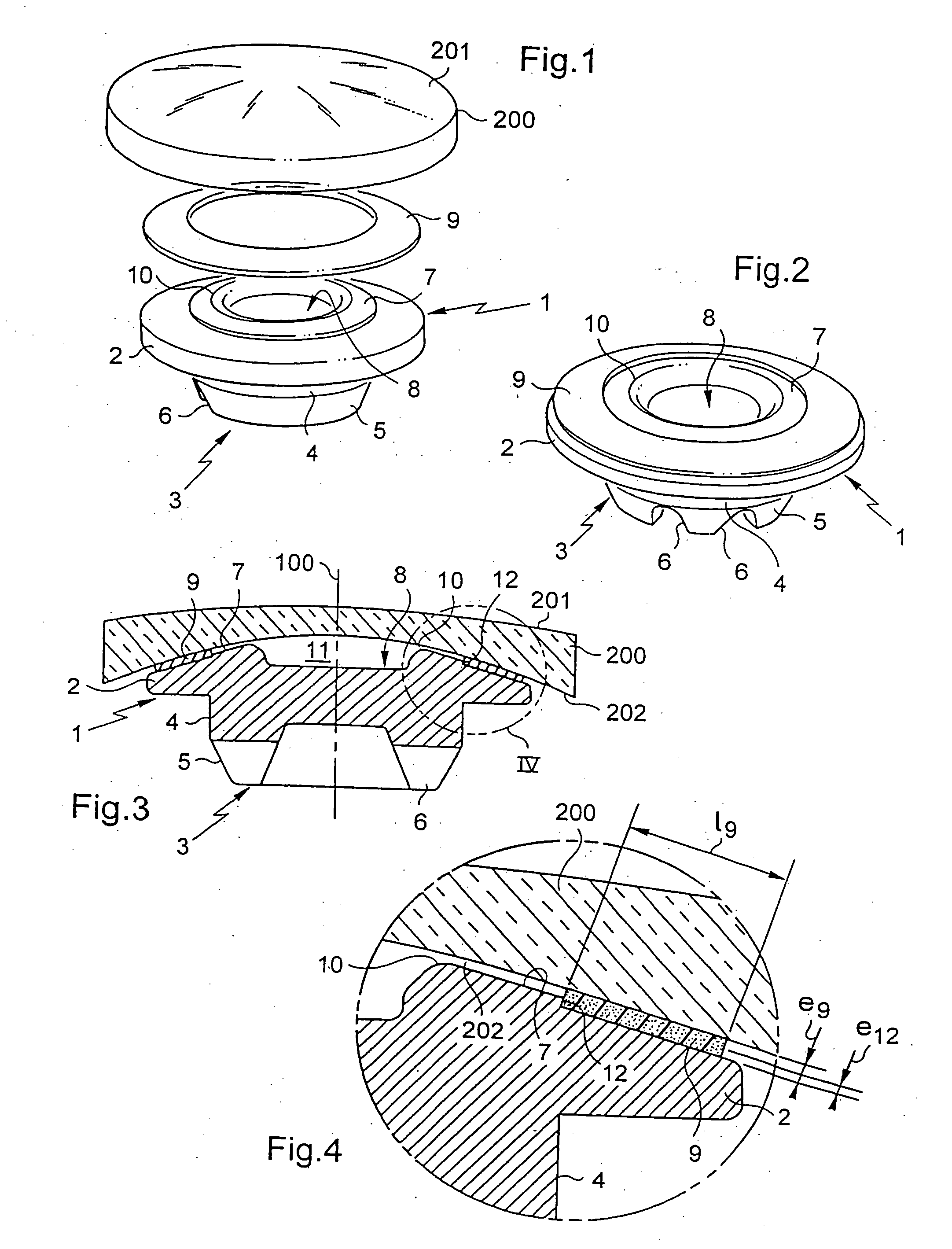
[0022]FIG. 1 is an overall exploded perspective view of a pneumatic blocking support in the invention;

[0023]FIG. 2 is a perspective view of the FIG. 1 support when assembled;

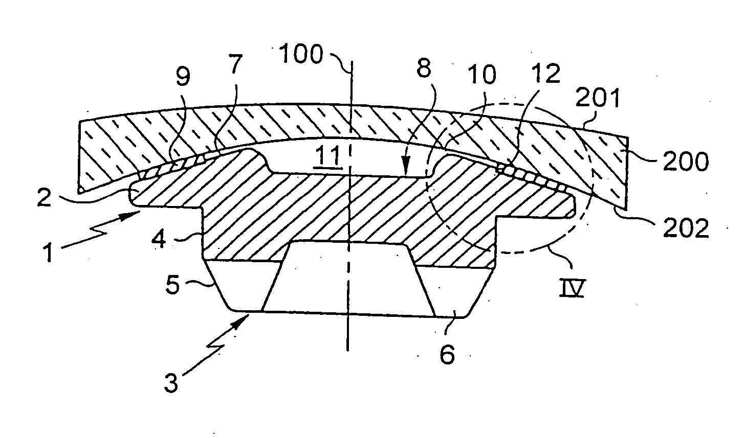
[0024]FIG. 3 is an axial section view of the support of FIGS. 1 and 2, on which there rests a lens prior to being blocked by means of suction;

[0025]FIG. 4 is a detail view showing zone IV of FIG. 3;

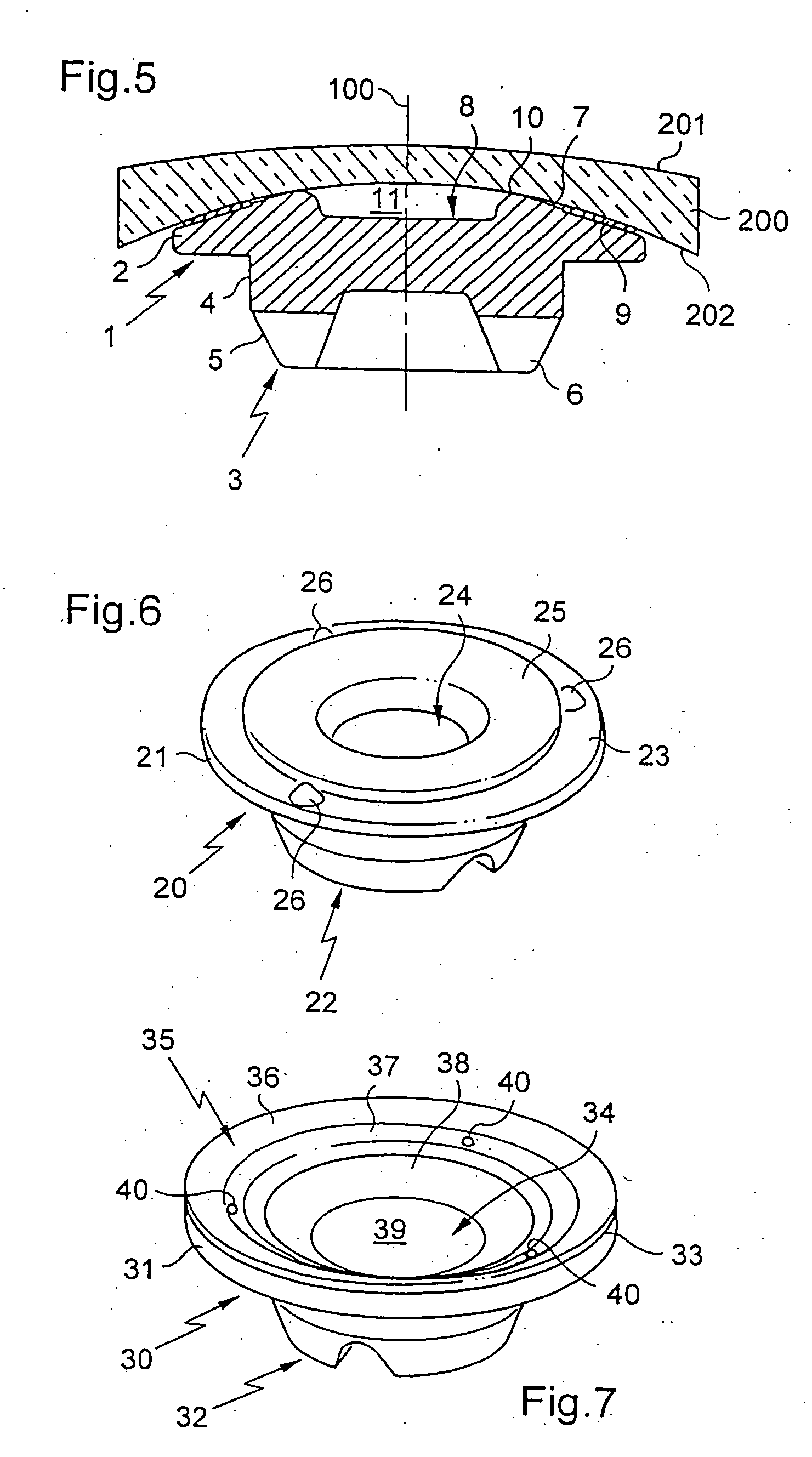
[0026]FIG. 5 is a view analogous to FIG. 3, after the lens has been blocked by suction;

second embodiment

[0027]FIG. 6 is a perspective view of a pneumatic blocking support in the invention; and

third embodiment

[0028]FIG. 7 is a perspective view of a pneumatic blocking support in the invention.

[0029] With reference to FIGS. 1 to 5, there is described a first embodiment of a support capable of using pneumatic action to block an optical lens 200, specifically an ophthalmological lens for spectacles, on a machine tool or a measurement device (not shown).

[0030] The support comprises a block 1 that is generally of circular symmetry about a central axis 100. The block 1 comprises two main portions: a plate 2 for receiving the lens 200 that is to be blocked, and projecting from the plate, coupling means 3 for securing the support to the nose of a machine tool or a measurement device.

[0031] The coupling means 3 are of conventional type and are themselves well known to the person skilled in the art; there is therefore no need to describe their structure or their operation in detail herein. It suffices to mention that, as shown in the figures, these means are in the form of a sleeve on an axis 100...


PUM


Abstract

The pneumatic blocking support which is used to block an optical lens (200) on a machine or device has means (3) for fixing it on a corresponding element of the machine or device. The blocking means comprise a central cavity (8) and a joint (9) having at least one annular part (9) against which the lens rests in order to define a depression chamber (11) with said cavity and joint. The blocking means comprise stop means (10) which are created in order to provide the optical lens with a rigid seat after the elastic compression of the joint.

Description

TECHNICAL FIELD TO WHICH THE INVENTION RELATES [0001] The present invention relates in general to fabricating optical lenses such as ophthalmological lenses, and / or lenses for sunglasses, objective lenses, etc. The invention relates in particular to blocking such a lens while it is being surfaced or inspected, and for this purpose it relates to a pneumatic blocking support for fixing on the nose of one or more machine tools or measurement or inspection devices in order to block the lens or a semi-finished blank of said lens on such a machine or device. TECHNOLOGICAL BACKGROUND [0002] The process for fabricating optical lenses, and more particularly corrective ophthalmological lenses, requires particularly high levels of care and precision. It generally comprises two main steps. Initially a semi-finished lens, also referred to as an optical blank or preform, is obtained by molding the synthetic or inorganic material that has been selected to constitute the basic substrate of the lens...

Claims


Application Information

Patent Timeline
IPC IPC(8): B24B41/06B24B13/005B29D11/00
CPCB24B13/0052B24B13/0057
Inventor ACHY, ARMANDCHANSAVOIR, ALAINBELLY, JEAN-FRANCOIS
Owner ESSILOR INT CIE GEN DOPTIQUE
Learn More