
Solution having biocidal activity

a biocidal and solution technology, applied in the field of biocidal solutions, can solve the problems of asthma and dermatitis in healthcare staff, inconvenient use of medical devices, and sensitive endoscopes, and achieve the effect of substantially eliminating the risk of mistakenly using solutions which are not adequately biocidal

Inactive Publication Date: 2007-05-17
PURICORE INT
View PDF0 Cites 34 Cited by
  • Summary
  • Abstract
  • Description
  • Claims
  • Application Information

AI Technical Summary

Benefits of technology

"The present invention provides a system for producing a biocidal solution that is within specification, on demand, and at or close to the site of use. The system ensures that the output solution has a predetermined level of available free chlorine, regardless of changes in water hardness, alkalinity, pressure, and other parameters. The system achieves this by maintaining a constant current and chloride ion throughput through the electrolytic cell. The level of available free chlorine can be set based on the biocidal properties required for the output solution. The system can control the pH of the output solution and can adapt to changes in the voltage across the cell. The system is adaptable to a wide range of applications and can be used in non-medical environments, such as processing of poultry and fish and general agricultural and petrochemical uses."

Problems solved by technology

However, this is not suitable for some medical apparatus, such as heat-sensitive endoscopes.
This can be unsatisfactory due to improper or incomplete disinfection.
Furthermore, exposure to glutaraldehyde fumes can cause asthma and dermatitis in healthcare staff.
Moreover, other disinfectants, such as chlorine dioxide and peracetic acid may suffer from similar handling problems as glutaraldehyde.
However, all of the systems described above have drawbacks and difficulties.
For example, the variable factors, such as the degree of electrolysis in the electrolytic cells, the concentration of dissolved salts and minerals and the flow rates, the fluctuations in electricity supply, ambient temperature and the variability of incoming water supplies present a barrier to ensuring a consistent supply of sterilising or, more correctly, biocidal solution.
This results in changes to the anolyte flow rate and consequently in changes to the electrochemistry taking place in the electrolytic cell.
This means that a cell which is calibrated to produce a biocidal solution of given composition in a first geographical location may not produce the same biocidal solution in a second location, making re-calibration necessary.
This is a time-consuming and laborious task.
A still further disadvantage of the apparatus described in the prior art is that they are prone to a high level of wastage.
This is especially pertinent where resources such as water are limited or costly.
In the Applicant's experience, none of the above systems is suited to providing a wholly reliable or autonomous supply of biocidal solution.
As will be readily appreciated, a “sterilising” solution which does not meet the required level of biocidal efficacy carries a risk of allowing an instrument to spread infection.
Moreover, the end user will not be able to detect by visual inspection alone whether the biocidal solution from any one of these systems is within or outside specification.

Method used


Image

  • Solution having biocidal activity
  • Solution having biocidal activity
  • Solution having biocidal activity

Examples


Embodiment Construction

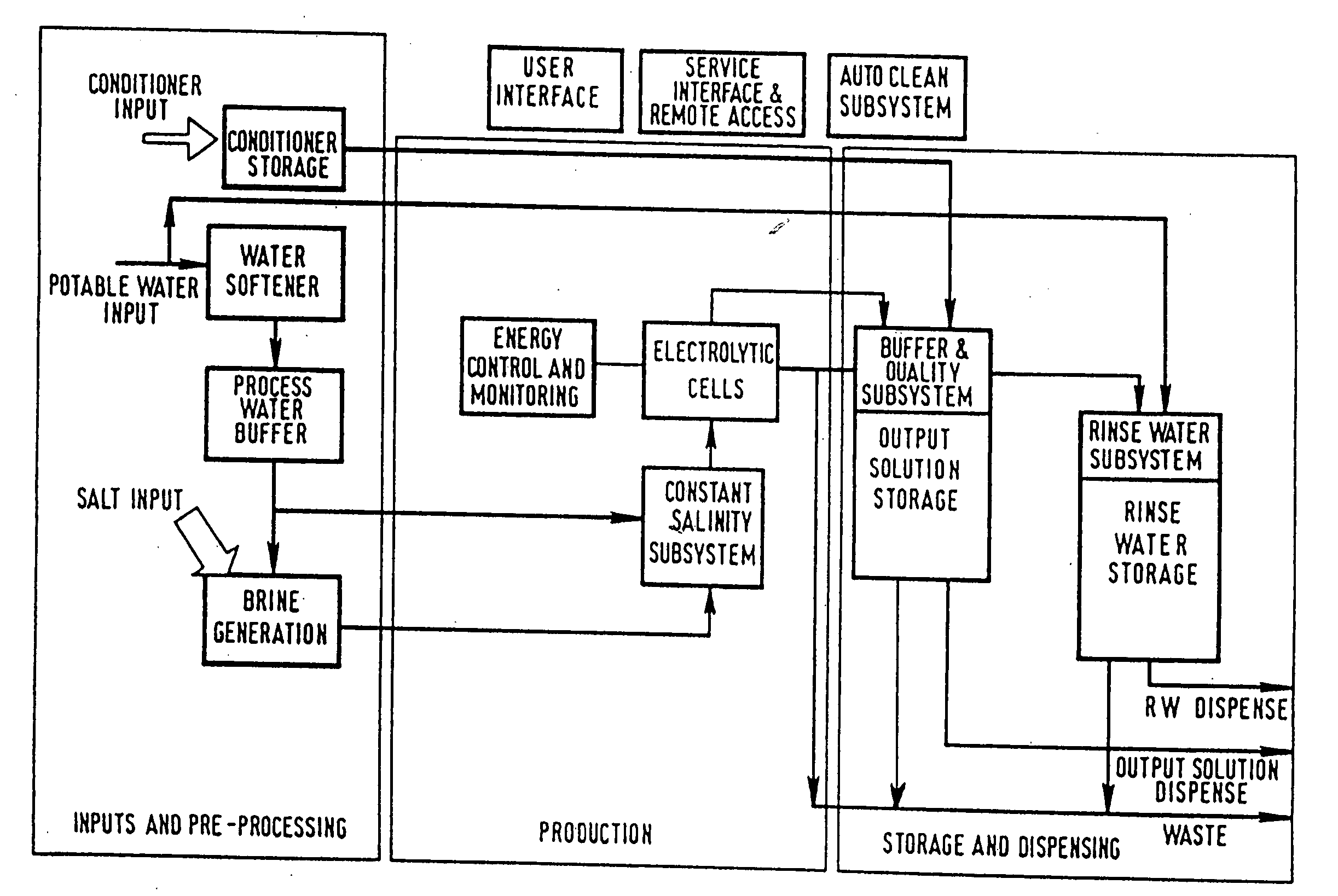
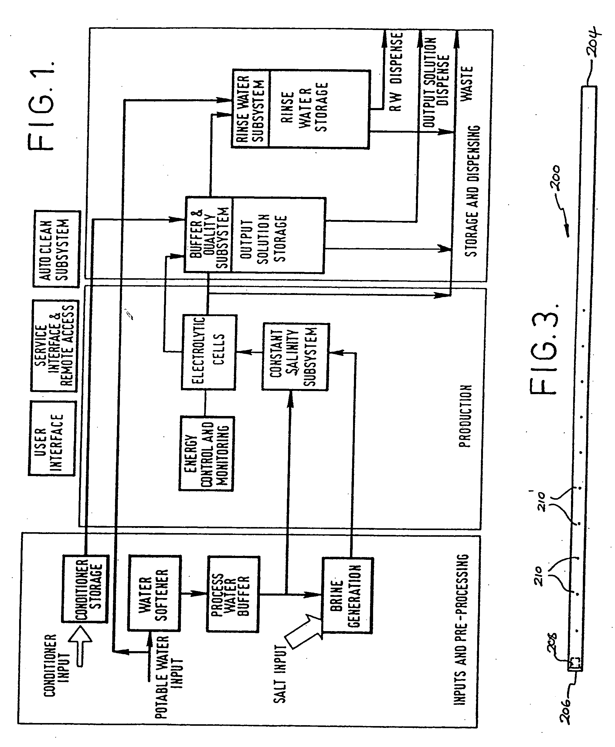
[0132] Referring first to FIG. 1, the schematic outline of the invention is broken down into three main processing stages, namely an inputs and pre-processing stage, a production stage and a storage and dispensing stage. While referred to as stages, it will of course be appreciated that the process of the invention may be carried out continuously.

[0133] In the first (inputs and pre-processing) stage, there is an input of potable water which, for the purpose of generating saline solution for use in the electrolytic cell, is first passed through a water softener zone where excessive magnesium and calcium ions are removed. The softened water is then passed into a process water buffer zone where it is held until required for use in the production of brine. Potable water input is also passed directly to the storage and dispensing stage for use in the preparation of bacteria-free rinse water, but for this purpose there is no need for the water to be softened prior to use.

[0134] The firs...


PUM

PropertyMeasurementUnit
surface areaaaaaaaaaaa
inner diameteraaaaaaaaaa
lengthaaaaaaaaaa

Abstract

A method and apparatus for the electrochemical treatment of an aqueous solution in an electrolytic cell is described. Output solution having a predetermined level of available free chlorine is produced by applying a substantially constant current across the cell between an anode and a cathode while passing a substantially constant throughput of chloride ions through the cell.

Description

CROSS-REFERENCE TO RELATED APPLICATIONS [0001] This application is a continuation of U.S. application Ser. No. 10 / 663,079, filed on Sep. 16, 2003, which is a divisional of U.S. application Ser. No. 09 / 633,665, filed Aug. 7, 2000, which claims priority to GB Application No. 9918458.2, filed on Aug. 6, 1999 and GB Application No. 9927808.7, filed on Nov. 24, 1999, all of which are incorporated by reference herein.BACKGROUND OF THE INVENTION [0002] The present invention relates, among other aspects, to a method of operating an electrochemical cell to produce a biocidal solution and apparatus for producing a biocidal solution by way of the electrolytic treatment of an aqueous chloride solution. [0003] In hospitals it is important to provide appropriate levels of sterility, particularly in operating theatres and other situations where invasive treatments are performed. Surgical instruments and other apparatus must be sterilised or disinfected, depending on their application, before use i...

Claims


Application Information

Patent Timeline
Patent Type & Authority Applications(United States)
IPC IPC(8): C25C1/02C02F1/00C02F1/42C02F1/461C02F1/467C02F9/00C25B9/19
CPCC02F1/46104C02F1/4618C02F1/4674C02F9/00C02F2001/425C02F2001/46142C02F2001/46185C02F2001/46195C02F2103/026C02F2103/22C02F2201/46115C02F2201/46125C02F2201/46145C02F2201/4618C02F2201/46185C02F2209/005C02F2209/008C02F2209/04C02F2209/05C02F2209/06C02F2209/42C02F2303/04C02F2303/20A61P43/00
Inventor BUCKLEY, ALANPOPOV, ALEXEY YUREVICHBELLAMY, MARTINCOLLINS, PHIL
Owner PURICORE INT
Learn More