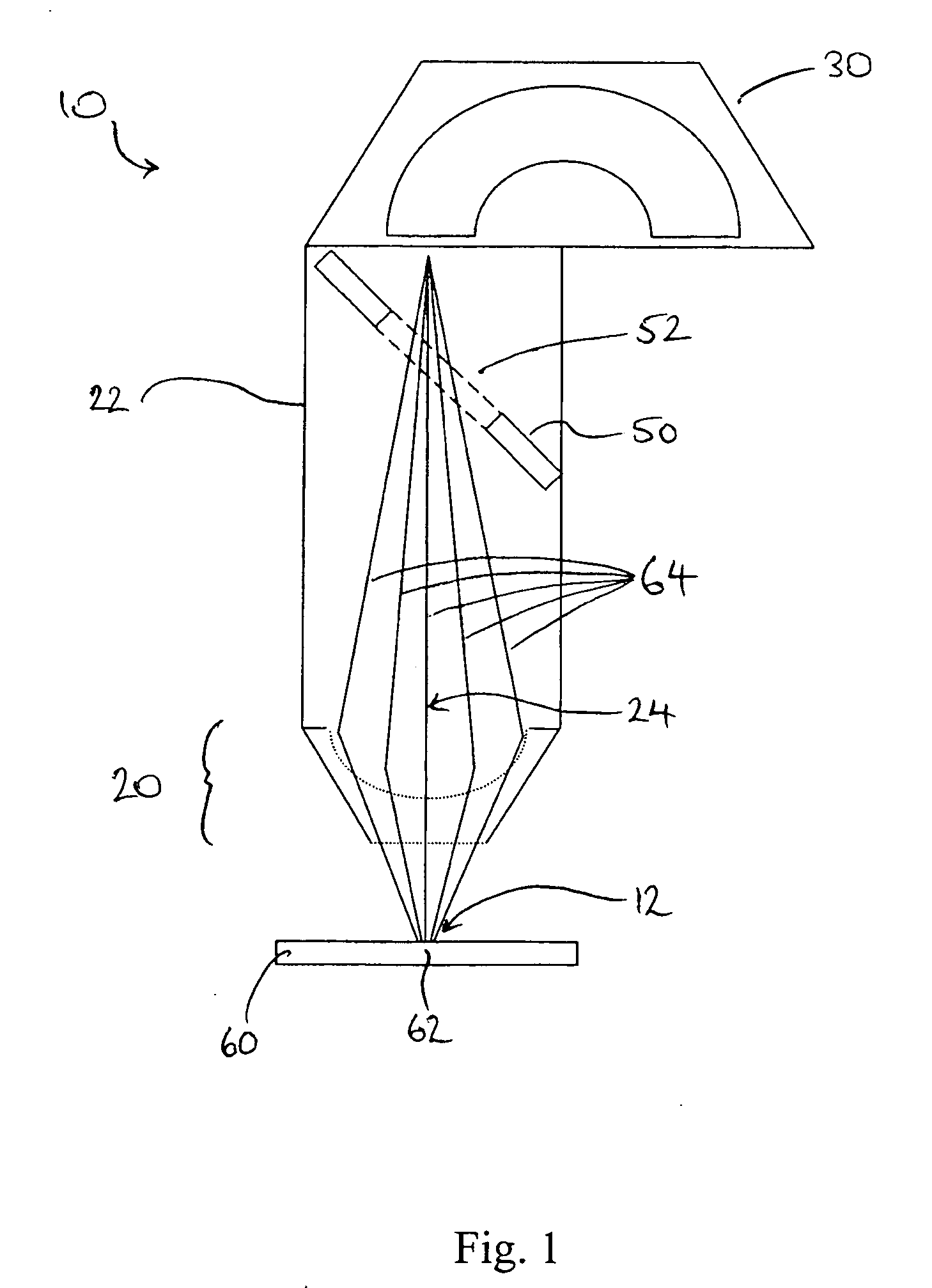
[0062] The collection lens arrangement 20 collects the secondary charged particles into the collection chamber 22 and causes the particles to converge, so that they are able to pass through the hole 52 in the mirror 50 and on to the spectroscopic
analyser 30. The converging effect of the collection lens arrangement 20 may be such that the secondary particles are focused to or towards a point, either within the collection chamber 22 or the
analyser 30. Alternatively, the converging effect may be such that the secondary particles are collimated into a narrow enough beam for passage through the hole 52 in the mirror 50. It is an
advantage of the invention that guiding or controlling the secondary particles in any of these ways through the collection chamber 22 and into the
analyser 30 does not significantly impair the collection efficiency of the spectrometer 10.
[0063]FIG. 1 shows an example in which the secondary particles are emitted with a wide range of angles from the area of analysis 62 of the sample. The emitted particles are disposed generally about the collection axis 24, which is normal to the analysis area 12 and therefore normal to the area of analysis 62 of the sample 60 which is located at the analysis area. At least a proportion of the secondary particles emitted from the surface are collected by the collection lens arrangement 20, which in this embodiment focuses them towards a point on the collection axis 24 at a downstream end of the collection chamber 22. It is noted that substantially all of the secondary particles received into the collection chamber 22 are directed through the hole 52 in the mirror 50 and onto the analyser 30.
[0064] A wide variety of analysers known in the art may be used as the spectroscopic analyser 30. For example, in
energy analysis and in particular XPS or AES, the analyser 30 may be either a toroidal electrostatic analyser or an electrostatic cylindrical mirror analyser, or the analyser may be a time-of-flight analyser, especially for SIMS applications. However, any energy or
mass analyser may be used, depending on the application.
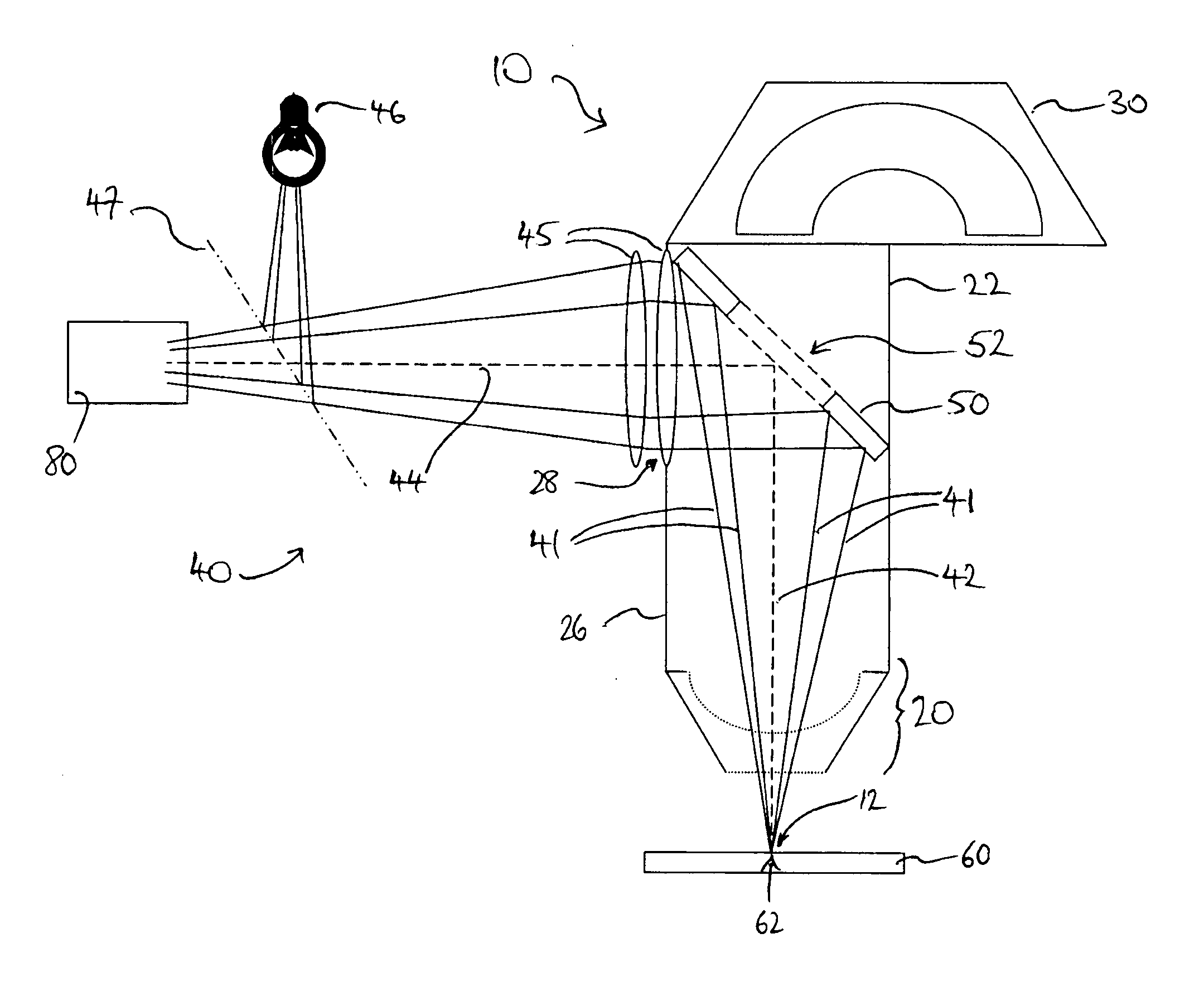
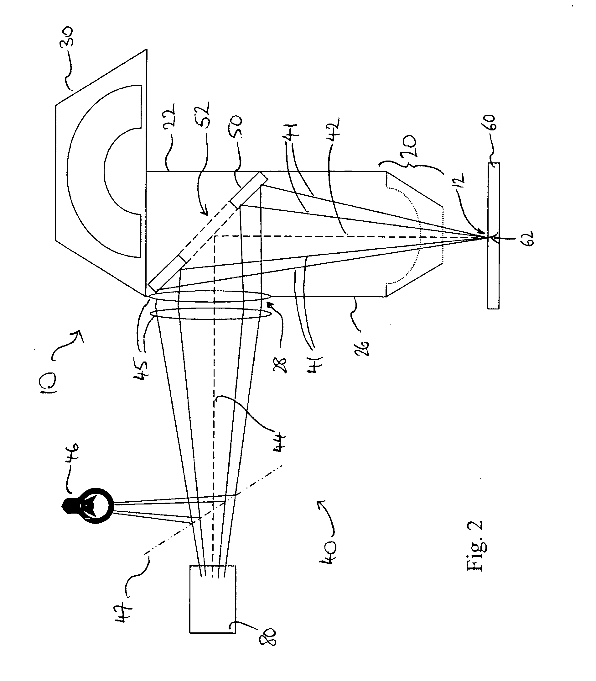
[0065]FIG. 2 shows a spectrometer 10, comprising a collection lens arrangement 20 provided in a collection chamber 22, at a first end adjacent an analysis area 12 of the spectrometer, a spectroscopic analyser 30 located at the other, downstream end of the collection chamber 22, and a mirror 50 having a hole 52 therein mounted towards the downstream end of the collection chamber, as in FIG. 1. The spectrometer 10 includes an
optical microscope 40, which is disposed about two optical axes in this embodiment. An objective
optical axis 42 extends normally from the analysis area 12 to the mirror 50, which is mounted at a 45° angle to the objective
optical axis. In this embodiment, the mirror 50 is centred on the objective
optical axis 42. Extending from the centre of the mirror 50, perpendicularly to the objective optical axis 42, is an imaging optical axis 44. Disposed along the imaging optical axis 44 are two imaging lenses 45—although only one, or more,
imaging lens may alternatively be used—and an
optical imaging device 80, such as a
CCD camera. Also disposed on the imaging optical axis 44, between the imaging device 80 and the mirror 50 is a partially reflective and partially transmissive element or pellicle 47, which is mounted at 45° to the imaging optical axis. A
light source 46 is provided perpendicularly to the imaging optical axis 44 and aligned with the pellicle 47.
[0066] The collection chamber 22 is provided with a vacuum optical window 28, which is optically transmissive, so as to allow light to pass out of the collection chamber therethrough. In this embodiment, although not necessarily so, the vacuum optical window 28 provided in the side wall 26 of the collection chamber 22 is itself an optical lens element 45. This has the benefit of reducing the number of optical components in the
microscope, thereby reducing cost and complexity.
[0067] In use, image light rays 41 emanating from an object at the analysis area 12, such as an area of analysis 62 of a sample 60, enter the collection chamber 22 through its entrance aperture and travel towards the mirror 50, the rays being generally disposed about the objective optical axis 42. Broadly speaking, the light rays 41 reaching the mirror 50 are reflected in a direction generally perpendicular to the objective optical axis 42, so that the reflected light rays 41 are then disposed generally about the imaging optical axis 44.

