Method for efficient transport of small liquid volumes to, from or within microfluidic devices

a microfluidic device and liquid volume technology, applied in the field of efficient transport, can solve the problems of high sensitivity of microscale analytical technologies, inability to efficiently load and deliver appropriate microscale samples, and low sensitivity of nmr (1000-fold less than mass spectrometry) problems, so as to avoid analyte loss, low loss, and high speed

Inactive Publication Date: 2007-05-24
NORTHEASTERN UNIV
View PDF15 Cites 35 Cited by
  • Summary
  • Abstract
  • Description
  • Claims
  • Application Information

AI Technical Summary

Benefits of technology

[0013] In the preferred embodiment of the method of the invention, an aliquot of a liquid that is not miscible with the sample, denominated an “immiscible carrier liquid,” is first introduced into a conduit through a microfluidic device. When an aliquot of the sample is subsequently introduced into the conduit, the sample forms a segment or “plug” in the microfluidic channel or capillary, following the carrier liquid. The carrier liquid is pumped or otherwise caused to flow through the channel, and the sample is carried from one location to another through the microfluidic channels without dilution or dispersion into the immiscible carrier liquid. The interior wall of the conduit (channel) is covalently coated with a suitable coating, so that the carrier liquid wets the conduit wall preferentially to the sample solvent. A film of the carrier liquid will then be retained on the channel wall as the sample plug is moved passed, so that the moving sample plug will not contact the conduit wall. This avoids losses of analyte either by binding of analyte molecules to the conduit wall or by bulk loss of sample as a film on the conduit wall.
[0014] Preferably, the microfluidic device is part of a conduit system, with attached tubing to transport samples onto and off of the device. Small liquid samples may thus be transported long distances through microfluidic plumbing and through such microdevices with very low losses, and at relatively high speed. As a specific example, if the immiscible carrier liquid is a fluorocarbon (FC), and the channel surface is fluorine-rich, the carrier liquid will wet the channel wall preferentially to both aqueous and organic (hydrophobic and hydrophilic) solvent samples. The desired effect may be obtained either by making a portion of the system, e.g., the attached tubing, of a fluorine-rich material such as a teflon (PTFE, ETFE, FEP, NGFP, etc.), or a channel wall, e.g., in the microdevice, may be coated with a fluorine-rich layer such as a fluoroalkyl silane coating on glass, silica, or plastic.

Problems solved by technology

The tremendous sensitivity of these microscale analytical technologies, however, is useless without the ability to efficiently load and deliver the appropriate microscale samples.
However, in pressure-driven liquid flow, a sample originating as a short volume segment of a conduit will disperse into a larger volume, with concomitant dilution, proportionally to the volume through which it is moved: the boundary layer at the conduit wall is immobile; however, flow at the center of the conduit is rapid.
However, the low sensitivity of NMR (1000-fold less than mass spectrometry) is problematic, particularly in LC-NMR where acquisition time is limited and compounds of interest may be a small fraction of the permissible column load.
For mass-limited samples, microcoil NMR probes offer up to a 500-fold sensitivity increase (Olson, 1995), however, efficiently loading microcoil probes is a challenge (Kautz, 2001).
An additional complication is that any motorized equipment must be located outside the magnet's fringe field, necessitating an additional 1-10 meters of capillary tubing, depending on the magnet's fringe field.
But the challenge of filling a 1 μL observed volume in a 5 μL flow cell through several meters of 50 micron capillary tubing (2 μL / meter) has severely limited microcoil NMR's sensitivity in practice.
Samples can be injected relatively quickly without dilution; however, the percentage of the injected sample that ultimately resides within the NMR coil observed volume during spectral analysis, is low.
Because it is not feasible to flush 50 micron capillaries longer than 1 meter with air, and larger capillaries have a prohibitively large volume, direct injection methods have only been implemented on microcoil probes manually.
Sharp gradients of analyte concentration near the NMR coil immediately after injection can cause poor line shape, and an equilibration time of 1-2 min may be required for line shape to sharpen as the analyte diffuses throughout the flow cell.
However, substantial challenges remain in putting this approach into practice (Macnaughtan, 2003).
Sample plugs are frequently lost or degraded in a variety of ways.
Principally, moving sample plugs leave a film of solvent on the wall of the conduit, e.g., capillary, and this film can consume about 2 μL of sample per meter of movement, which is completely prohibitive.
All of this lost material can mix with subsequent plugs, resulting in high carryover (Patton et al., 1997).
Both of these effects increased with increasing capillary size, where the outward pressure of the curved surface of the plug was insufficient to hold the plug against the conduit wall in capillaries over 300 μm diameter.

Method used


Image

  • Method for efficient transport of small liquid volumes to, from or within microfluidic devices
  • Method for efficient transport of small liquid volumes to, from or within microfluidic devices
  • Method for efficient transport of small liquid volumes to, from or within microfluidic devices

Examples


example i

Feasibility Studies and Method Development

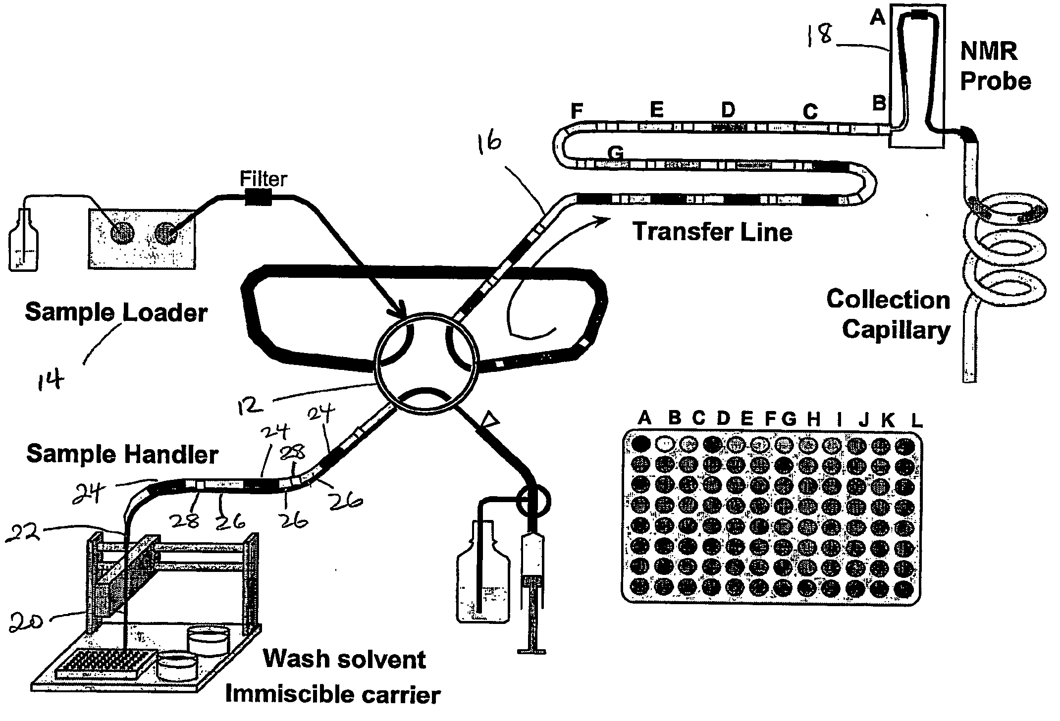
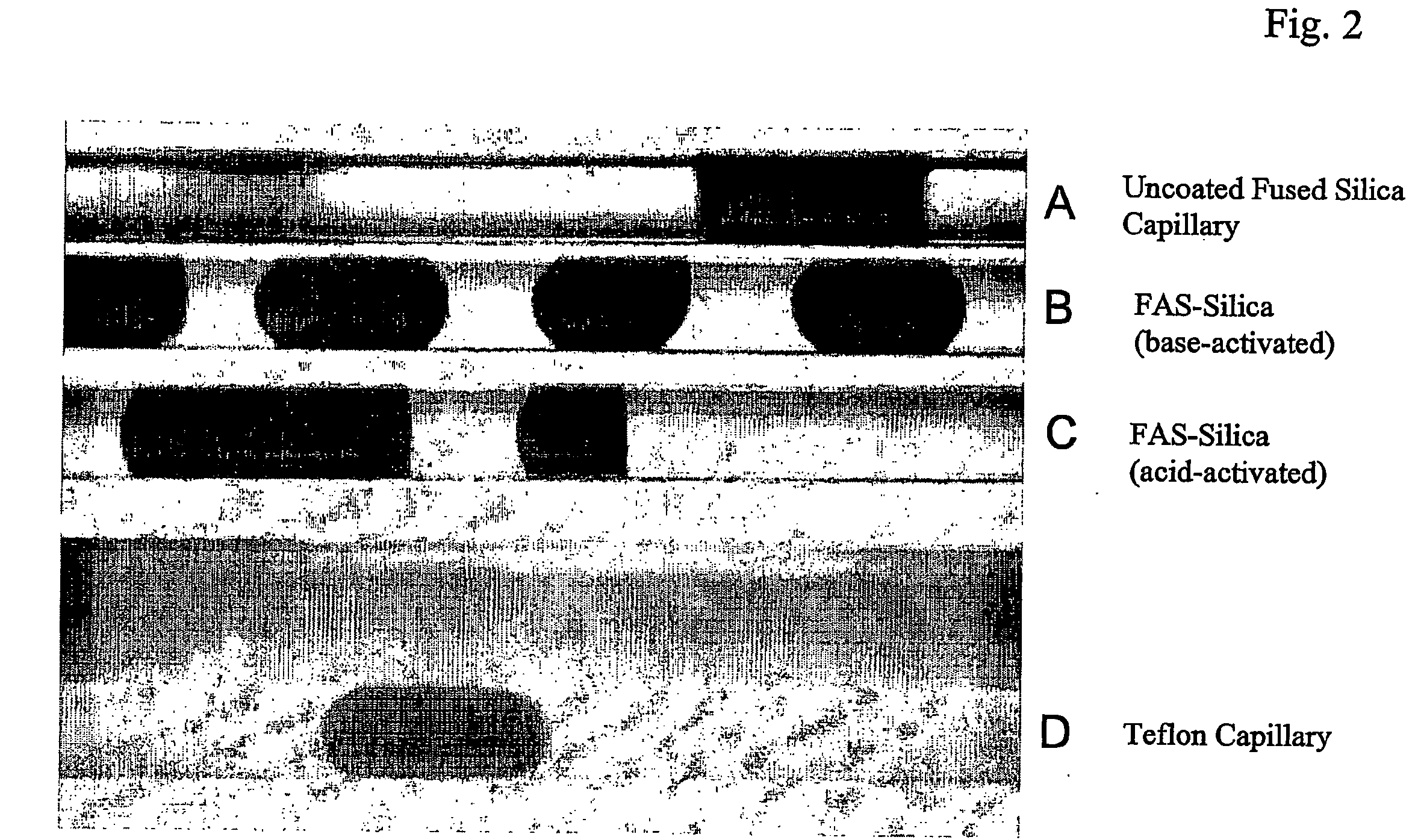
[0047] Preliminary studies were made, observing the movement of DMSO sample plugs using FC 43 as the carrier fluid in capillaries of several different materials. In the Teflon capillary, FC 43 was the continuous phase: DMSO plugs did not contact the capillary wall and could be moved through several meters with no detectable carryover (<0.1%) or losses at all flow rates tested (0-20 μL / min). In plain fused-silica capillary, DMSO was the continuous phase, retention of a DMSO film depleted sample plugs by 2 μL for each meter of movement (in 200-μm capillary). In PFOS-coated silica capillary, neither phase was continuous: a DMSO film was not retained, so sample losses were negligible at modest flow rates (1-10 L / min); however, carryover of minute droplets could occur (10-100 nL / m) if imperfections existed in the coating. It was also found necessary to push the sample train through the NMR probe under positive pressure rather than to pull sample...

example ii

Performance of the Automated SFA-NMR System

[0049] The performance of the system was evaluated by loading samples and acquiring spectra from 96-well plates with 3 μL / well of test library compounds (30 mM in DMSO-d6) interspersed with standards for assessing carryover and line shape. Automated analysis completed in 2.5 hr / plate, plus 24 min to initialize the queue in which four trains were drawn and two were injected. This initialization time is reported separately because it applied to the first plate but not to subsequent plates of continuous high-throughput operation. Spectra were output at rates of 1 / min along each train of four samples. The sample change and wash was completed in 35 s, NMR acquisition was set to 16 s, and the automation software required 10 s of execution and dead time. Sustainable throughput was 1.5 min / sample due to the time required to draw a new train from the needle line into the sample loop and to advance the queue through the gap between trains (105s).

[0...


PUM

PropertyMeasurementUnit
dead volumeaaaaaaaaaa
volumeaaaaaaaaaa

Abstract

Methods are presented for realizing zero-dispersion segmented flow for transfer of small microfluidic samples onto or within microfluidic analysis or processing devices. Where fluidic systems are in whole or in part made of materials favorable to the zero-dispersion conditions for an indicated solvent/carrier fluid system, the system may be covalently coated to impart the necessary surface properties. This invention is demonstrated in an embodiment where 1 microliter samples (6) are robotically prepared and transferred through 3 meters of capillary tubing (4) to a microcoil NMR probe.

Description

CROSS REFERENCE TO RELATED APPLICATIONS [0001] This application claims the priority of U.S. Provisional Application No. 60 / 528,410 filed Dec. 10, 2003 entitled, METHOD FOR EFFICIENT TRANSPORT OF SMALL LIQUID VOLUMES IN MICROFLUIDIC DEVICES, the whole of which is hereby incorporated by reference herein.STATEMENT REGARDING FEDERALLY SPONSORED RESEARCH OR DEVELOPMENT [0002] N / A BACKGROUND OF THE INVENTION [0003] In the last 50 years, and especially in the last decade, there has been a remarkable trend towards both the automation and the miniaturization of chemical analysis and electromechanical systems. The limits of detection of primary analytical methods have improved by many quantum leaps. Mass spectrometry can detect attomoles of sample using nanospray methods. Nuclear Magnetic Resonance (NMR) can now detect pmoles of analyte using 5 nL microcoil probes (Olson, 1995), a 500-fold improvement over 1980's technology. Capillary electrophoresis with laser-induced fluorescence detection ...

Claims


Application Information

Patent Timeline
Patent Type & Authority Applications(United States)
IPC IPC(8): G01N33/22B01L3/00B01L3/02C02F1/40C25D1/12G01NG01N1/00G01N1/10G01R33/30
CPCB01L3/502784B01L2200/027B01L2200/0673B01L2300/0838B01L2300/165G01N35/1095Y10T436/2575G01R33/307Y10T436/24Y10T436/208339Y10T436/25Y10T436/117497G01R33/302
Inventor KAUTZ, ROGER A.KARGER, BARRY L.
Owner NORTHEASTERN UNIV
Why Eureka
Try Eureka