
Resin composition for optical wiring, and optoelectronic circuit board

a technology of optical wiring and composition, applied in the direction of circuit optical details, optical elements, instruments, etc., can solve the problems of insufficient integration of materials with electric wiring boards, noise and inter-channel crosstalk of emi (electromagnetic interference), and the difficulty of further speedup and densification, so as to reduce the dependence, reduce the loss of optical propagation, and the effect of durable against temperature chang

Inactive Publication Date: 2007-06-28
TORAY IND INC
View PDF2 Cites 16 Cited by
  • Summary
  • Abstract
  • Description
  • Claims
  • Application Information

AI Technical Summary

Benefits of technology

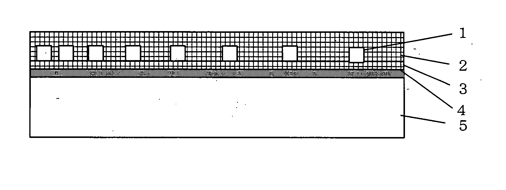
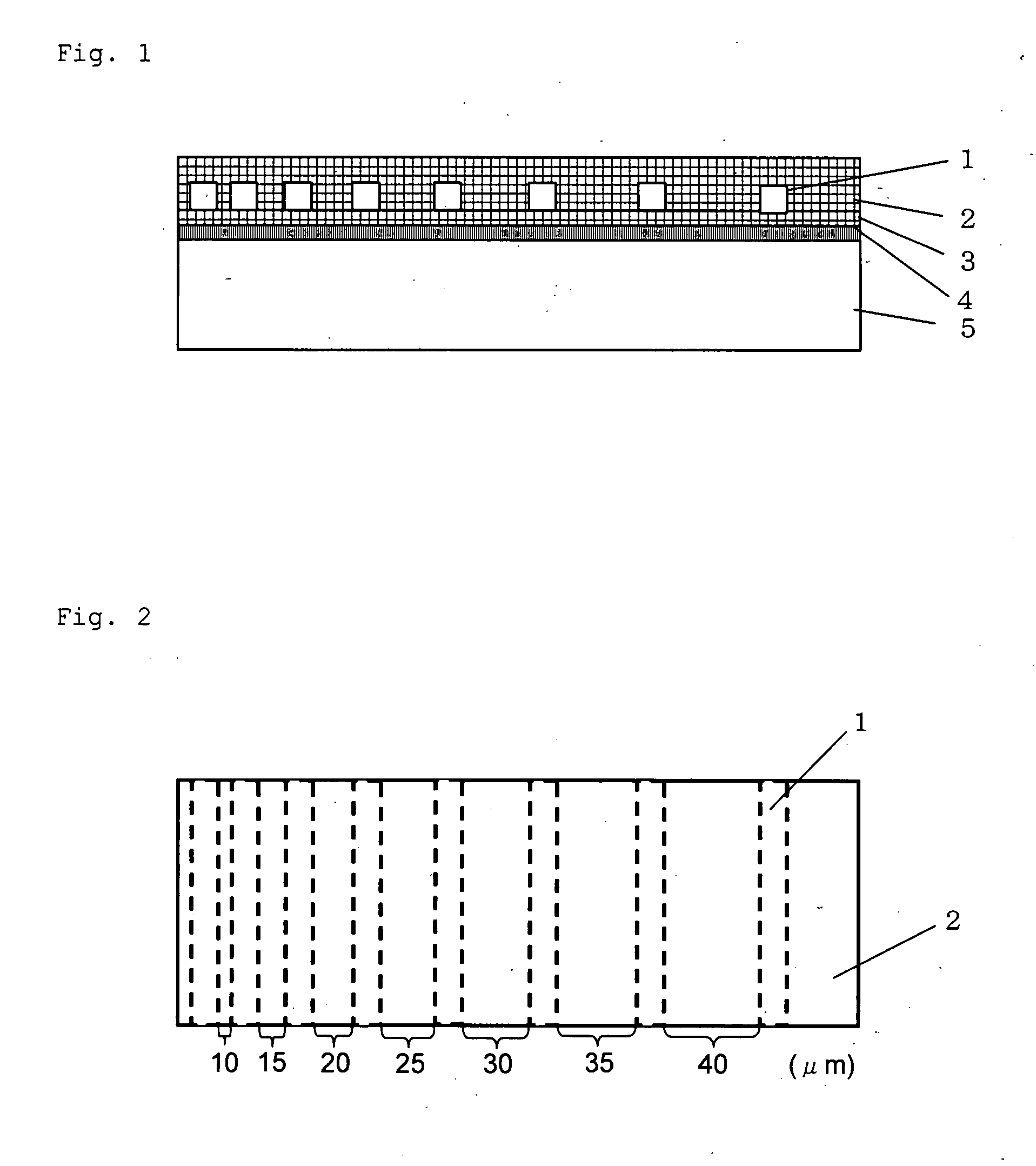
[0022] If the resin composition for optical wiring of this invention is used, an optical wiring layer having a thermal expansion coefficient little different from that of the electric wiring board, small in the dependency of its refractive index on the temperature, and suitable for integration with the electric wiring layer can be obtained. If the resin composition of this invention is used, an optoelectronic circuit board small in optical propagation loss, durable against temperature change and stable in light transmission characteristics can be obtained.

Problems solved by technology

In the conventional signal transmission over relative short distances, for example, between boards in each equipment or between chips on each board, electric signals are used, but further speedup and further densification are already difficult.
For (1) further speedup, the signal delay due to the CR (C=electrostatic capacity of wiring, R=resistance of wiring) time constant of wiring is a problem, and for (2) further densification of electric wiring, EMI (Electromagnetic Interference) noise and inter-channel crosstalk are problems.
None of the materials is adequate for integration with an electric wiring board for any of such reasons that the heat treatment temperature for solidification is too high, that heat resistance is insufficient, and that the thermal expansion coefficient is too large.
However, they have such problems that the size of the particles used is large, and / or that since the refractive index of titanium oxide or aluminum oxide is larger than that of the resin, the Rayleigh scattering owing to the particles is large, hence as a result, the optical propagation loss is likely to be large.

Method used


Image

  • Resin composition for optical wiring, and optoelectronic circuit board
  • Resin composition for optical wiring, and optoelectronic circuit board
  • Resin composition for optical wiring, and optoelectronic circuit board

Examples


example 1

[0087] A liquid epoxy resin (“Product #314” produced by Epoxy Technology Inc.) and an organo silica sol with an average particle size of 12 nm dispersed in γ-butyrolactone were mixed using a ball mill to achieve a ratio by volume of epoxy resin:silica=57:43 after curing. A quartz substrate was coated with the mixture using a spin coater, and it was dried in air using an oven at 80° C. for 1 hour, and heated in nitrogen at 150° C. for 1 hour for curing, to obtain a 10 μm thick sample for measurement of refractive index and optical propagation loss. The refractive index of the obtained sample at room temperature at a wavelength of 0.837 μm was 1.484, and the optical propagation loss was 0.49 dB / cm. Separately, a sample of the epoxy resin alone was produced as described above, and its refractive index was 1.51. From these values, the refractive index of silica particles was calculated and found to be 1.45.

[0088] The temperature was changed from 25° C. to 90° C., to measure the change ...

examples 2 to 8

[0090] Samples were prepared and evaluated as described for Example 1, except that the compositions and conditions shown in Table 1 were used. Table 1 shows the evaluation results.

example 9

[0091] Samples were prepared as described for Example 1, except that a slurry with aluminum oxide dispersed in methyl isobutyl ketone solvent was used instead of the organo silica sol, and that it was mixed to achieve a ratio by volume of epoxy-resin:aluminum oxide=60:40 after curing. The measurement wavelength used was 0.85 μm. The evaluation results are shown in Table 1.


PUM

PropertyMeasurementUnit
wavelengthaaaaaaaaaa
temperatureaaaaaaaaaa

Abstract

This invention is a resin composition for optical wiring, comprising an inorganic filler with an average particle size of 1 nm to 100 nm and a resin, having a ratio nf / nr (where nf is the refractive index of the inorganic filler and nr is the refractive index of the resin) of 0.8 to 1.2, a thermal expansion coefficient of −1×10⁻⁵ / ° C. to 4×10⁵ / ° C., and a true dependency value of its refractive index on the temperature of −1×10⁻⁴ / ° C. to 1×10⁻⁴ / ° C. in a temperature range from −20° C. to 90° C., and substantially incapable of absorbing light in a wavelength range from 0.6 to 0.9 μm or from 1.2 to 1.6 μm. This invention also provides an optoelectronic circuit board.

Description

[0001] This application is a continuation of international application PCT / JP2005 / 016075 filed Sep. 2, 2005, which claims priority of Japanese patent application No. 2004-260812 filed Sep. 8, 2004, each of which is incorporated herein by reference. [0002] 1. Technical Field [0003] The present invention relates to an optical wiring material suitable for integration with an electric wiring board, and to a optoelectronic circuit board. This optical wiring can be used as the “on-board optical wiring” (optical interconnection) that allows high speed signal transmission between LSIs (Large Scale Integrated circuits) by optical signals. [0004] 2. Background Art [0005] The ever progressing LSI technology has allowed higher information processing speed and larger integration scale. As a result, microprocessors are showing higher performance and memory chips are having larger capacities at rapid paces. Further, the high functions of these LSIs are already used in presently commercially availa...

Claims


Application Information

Patent Timeline
Patent Type & Authority Applications(United States)
IPC IPC(8): G02B6/00
CPCG02B6/1221H05K1/0274H05K2201/0209H05K2201/068C08K7/08
Inventor NONAKA, TOSHIHISAASAHI, NOBORUTATSUTA, YOSHIKO
Owner TORAY IND INC
Learn More