Method for treating exhaust gas and apparatus for treating exhaust gas

Inactive Publication Date: 2007-07-12
TAIYO NIPPON SANSO CORP +1
View PDF10 Cites 10 Cited by
  • Summary
  • Abstract
  • Description
  • Claims
  • Application Information

AI Technical Summary

Benefits of technology

[0025] Moreover, since the exhaust gas is made to flow in the form of a viscous flow during flow of the exhaust gas under reduced pressure, pressure loss can be reduced, and gas components in an excited state can be transported to the plasma device through comparatively narrow lines. Thus, the amount of space required for the lines from the first exhaust pump of the production equipment to the plasma device can be decreased. Allowing the exhaust gas to flow in the form of viscous flow under reduced pressure means that the flow rate of the exhaust gas through the lines can be increased even for the same Reynolds number. Consequently, gas components in an excited state are able to reach the plasma device in a comparatively short period of time, thereby making it possible to prevent deactivation. Moreover, since exhaust gas is allowed to flow in the form of viscous flow, although collisions between excited gas molecules occur frequ

Problems solved by technology

These reaction products contained in exhaust gas have a high global warming potential, and are not allowed to be discharged as is, but rather are required to undergo detoxification treatment prior to being discharged.
These solid reaction products cause clogging of exhaust lines.
Although there are cases in which

Method used


Image

  • Method for treating exhaust gas and apparatus for treating exhaust gas
  • Method for treating exhaust gas and apparatus for treating exhaust gas
  • Method for treating exhaust gas and apparatus for treating exhaust gas

Examples


example 1

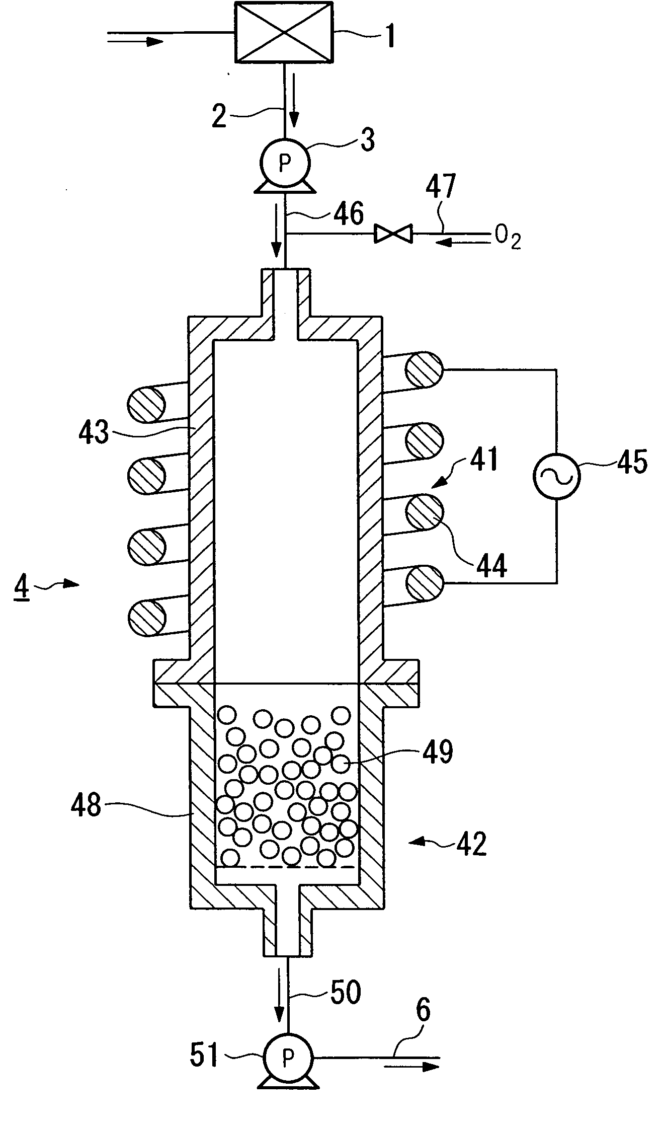
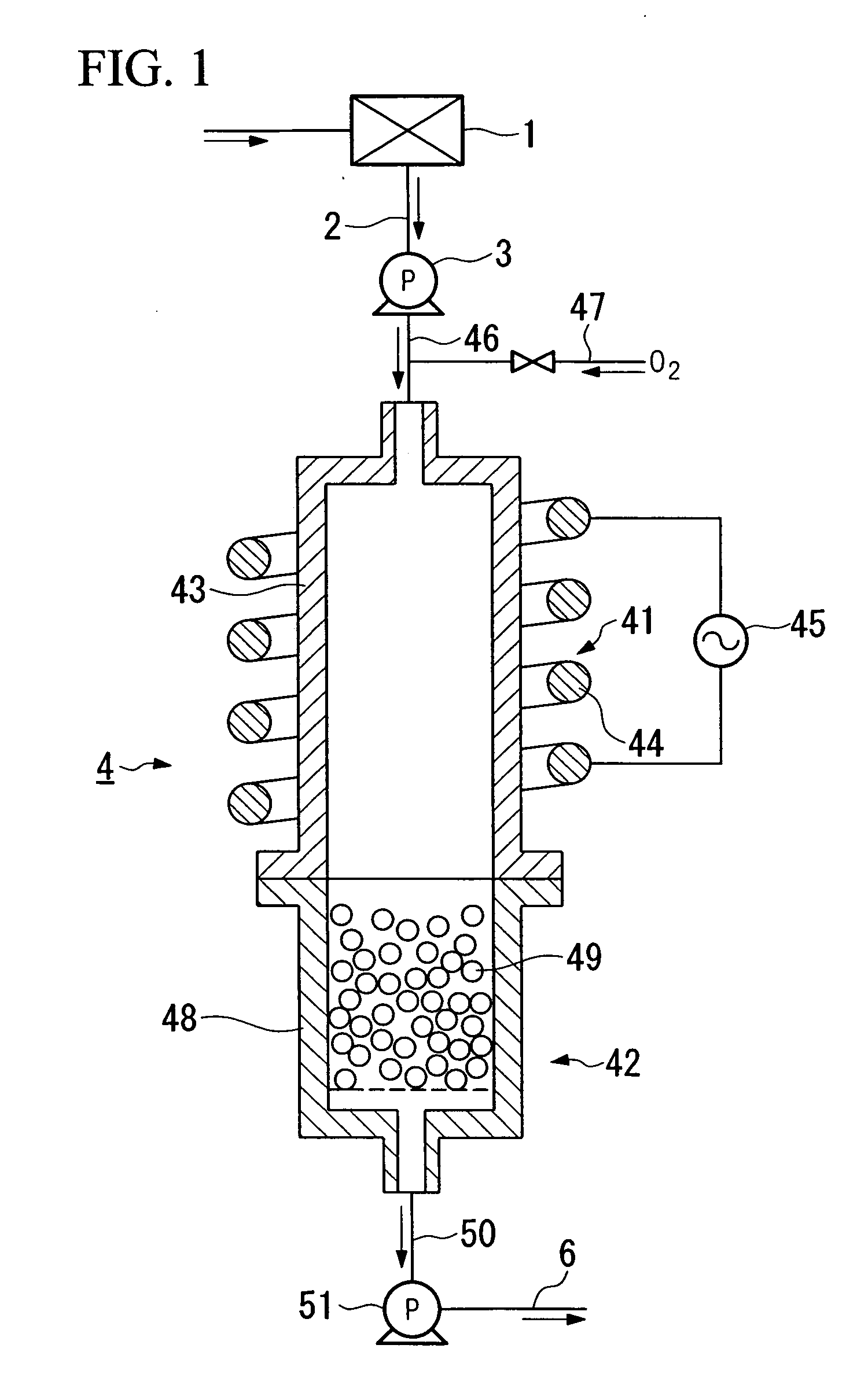
[0084] Exhaust gas from semiconductor device production equipment 1 was treated using the treatment apparatus shown in FIG. 1. An alumina cylindrical tube having an inner diameter of 40 mm was used for treatment tube 43 of plasma treatment unit 41, this was wound with a high-frequency coil 44, and a high-frequency current having a frequency of 4 MHz and maximum output of 1.2 kW was applied thereto from alternating current power supply 45 to generate inductively coupled plasma within treatment tube 43.

[0085] In addition, a bottomed cylinder made of quartz having an inner diameter of 40 mm and length of 150 mm was used for reactor 48 of reaction removal unit 42, and the inside thereof was filled with 300 g of particulate calcium oxide having a grain diameter of about 1 mm to a void fraction of 50% by volume.

[0086] Exhaust gas in an excited state was introduced from semiconductor device production equipment 1 into treatment tube 43 through feed line 46 by operating booster pump 3 and...

example 2

[0092] Exhaust gas having a composition of 20% Ar, 78% Xe, 0.1% GeH4, 0.1% B2H6 and 1.8% SiH4 was introduced into treatment tube 43 at a pressure of 50 Torr and flow rate of 200 SCCM using the same treatment apparatus as Example 1. Simultaneous thereto, oxygen at normal pressure was introduced from oxygen supply line 47 into reaction tube 43 at a flow rate of 10 SCCM to generate plasma within treatment tube 43 and degrade the harmful gas components in the exhaust gas by oxidative degradation. Subsequently, the exhaust gas was contacted with calcium oxide to remove the harmful gas components in reaction removal unit 42 in the same manner as Example 1.

[0093] When the amounts of GeH4, B2H6 and SiH4 in the exhaust gas discharged from discharge line 50 were quantified, the amount of GeH4 was less than 3 ppm (detection lower limit), the amount of B2H6 was less than 2 ppm (detection lower limit), and the amount of SiH4 was less than 3 ppm (detection lower limit).

example 3

[0094] Exhaust gas from semiconductor device production equipment 1 was treated using the treatment apparatus shown in FIG. 1. An alumina cylindrical tube having an inner diameter of 40 mm was used for treatment tube 43 of plasma treatment unit 41, this was wound with a high-frequency coil 44, and a high-frequency current having a frequency of 2 MHz and maximum output of 1.5 kW was applied thereto from alternating current power supply 45 to generate inductively coupled plasma within treatment tube 43. In addition, a bottomed cylinder made of stainless steel having an inner diameter of 40 mm and length of 150 mm was used for reactor 48 of reaction removal unit 42, and the inside thereof was filled with 20 kg of particulate calcium oxide having a grain diameter of 3 mm to a void fraction of 50% by volume.

[0095] Exhaust gas in an excited state was introduced from semiconductor device production equipment 1 into treatment tube 43 through feed line 46 by operating booster pump 3 and bac...


PUM

PropertyMeasurementUnit
Pressureaaaaaaaaaa

Abstract

In the exhaust gas treatment method of the present invention, exhaust gas in an excited state in semiconductor device production equipment is introduced into a plasma treatment unit of a treatment unit under reduced pressure, introduced into a reactor of a reaction removal unit while maintained in an excited state by plasma generated in the plasma treatment unit, and is reacted with a reaction remover composed of particulate calcium oxide filled into the reactor to remove harmful gas components in the exhaust gas. Exhaust gas may also be reacted with the reaction remover after having degraded the harmful gas components by oxidative degradation in the presence of plasma by supplying oxygen to the plasma treatment unit.

Description

TECHNICAL FIELD [0001] The present invention relates to a method for treating exhaust gas and apparatus for treating exhaust gas to remove harmful gas components present in exhaust gas discharged from production equipment used in the production of semiconductor devices, flat panel display devices, solar cells or magnetic thin plates. [0002] The present application claims priority of Japanese Patent Application No. 2004-20975, filed on Jan. 29, 2004, the content of which is incorporated herein by reference. BACKGROUND ART [0003] Exhaust gas discharged from the aforementioned production equipment contains Ar along with other reaction products such as CF4, C2F6 and SiF4. These reaction products contained in exhaust gas have a high global warming potential, and are not allowed to be discharged as is, but rather are required to undergo detoxification treatment prior to being discharged. In addition, high molecular weight reaction products are also formed by exposing the exhaust gas to at...

Claims


Application Information

Patent Timeline
IPC IPC(8): B01D53/68B01J19/08B01J19/12B01J3/00
CPCB01J19/088B01J2219/0894B01J2219/0892B01J2219/0883B01D53/68B01D53/34
Inventor OHMI, TADAHIROHASEGAWA, HIDEHARUISHIHARA, YOSHIOSUZUKI, KATSUMASA
Owner TAIYO NIPPON SANSO CORP
Why Eureka
Try Eureka