Ceramic support capable of supporting a catalyst, a catalyst-ceramic body and processes for producing same

a ceramic support and catalyst technology, applied in the direction of catalyst activation/preparation, metal/metal-hydroxide catalysts, chemical/physical processes, etc., can solve the problem of reducing the thermal capacity of the honeycomb structure as a whole, disadvantageously reducing the strength of the cordierite honeycomb structure, and reducing the amount of catalyst components. , to achieve the effect of low pressure loss, low thermal capacity and high thermal shock resistan

Inactive Publication Date: 2007-07-26
NIPPON SOKEN +1
View PDF36 Cites 82 Cited by
  • Summary
  • Abstract
  • Description
  • Claims
  • Application Information

AI Technical Summary

Benefits of technology

[0013] The ceramic support of the present invention is preferably a cordierite honeycomb structure comprising cordierite, the theoretical composition of which is 2MgO.2Al2O3.5SiO2, as the main component and having a honeycomb shape. Since the diameter of an ion of a catalyst component is usually in the order of about 0.1 nm, a cordierite honeycomb structure preferably has a diameter or width of the fine pores formed on the surface which is up to 1000 times, preferably 1 to 1000 times the above ion diameter or about 0.1 nm, that is, 0.1 to 100 nm, and a depth of the fine pores which is not smaller than a half of the diameter of an ion of a catalyst component, that is, 0.05 nm or more. By having the above predetermined number of such fine pores, the ceramic support of the present invention can directly support a required amount of a catalyst component with a required strength being maintained.
[0058] Moreover, in the present invention, a metal having a catalyst captivity may be substituted for a constitutional element of a cordierite honeycomb structure, to obtain a catalyst-ceramic body. In this case, cordierite materials in which some the Si, Al and Ng sources are replaced by a compound containing a metal having a catalyst activity, preferably a noble metal such as Pt, Pd or Rd in place of Si, Al or Mg of the cordierite-constituting elements, are used. Such cordierite materials are formed into a shape, heated to remove an organic binder and then fired to form a ceramic catalyst body. The firing atmosphere may be a reducing pressure atmosphere having a pressure of 4000 Pa or less, a reducing atmosphere such as a hydrogen atmosphere, or an oxygen-containing or an oxygen-free atmosphere. If a metal having an oxygen storage capacity such as Ce is used also as a substituting metal, in addition to a metal having a catalyst activity, the catalyst-ceramic body can support a catalyst component as obtained by the above process is a catalyst-ceramic body excellent in cleaning performance, which supports a required amount of a catalyst component directly thereon with a narrow space therebetween, without a coating of γ-alumina. Specifically, a catalyst component may be supported until the content of the metal element in the catalyst-ceramic body supporting the catalyst component, becomes 0.01% by weight, and the average space between the catalyst component particles (particles of catalyst component ion and catalyst metal, etc.) supported on the catalyst-ceramic body is as small as 0.1 to 100 nm. This means that with the same supporting amount of a catalyst component, the particle size of the catalyst component particles become smaller and the number thereof larger, which results in a denser distribution of the catalyst component on the entire surface of the ceramic support and the catalyst exhibits its performance more effectively.

Problems solved by technology

This is because a cordierite honeycomb structure has a relatively small specific surface area such that a sufficient amount of a catalyst component cannot be supported thereon.
However, even if the thickness of cell walls of a cordierite honeycomb structure is reduced, to have a small thermal capacity, the amount of a coating of γ-alumina does not decrease, resulting in lowering the effect of reducing the thermal capacity of the honeycomb structure as a whole.
Although it is mentioned that this method allows increase in the specific surface area from 1 m2 / g to about 30 m2 / g, this method disadvantageously decreases the strength of the cordierite honeycomb structure.
Therefore, the above method in JPP'338 does not provide an improved effect in reducing the thermal capacity of a catalyst support, considering the fact that a cordierite honeycomb structure having a cell wall thickness of 85 μm at a cell density of 400 cpsi can be produced at present.

Method used


Image

  • Ceramic support capable of supporting a catalyst, a catalyst-ceramic body and processes for producing same
  • Ceramic support capable of supporting a catalyst, a catalyst-ceramic body and processes for producing same
  • Ceramic support capable of supporting a catalyst, a catalyst-ceramic body and processes for producing same

Examples


example 1

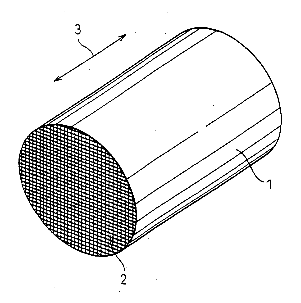
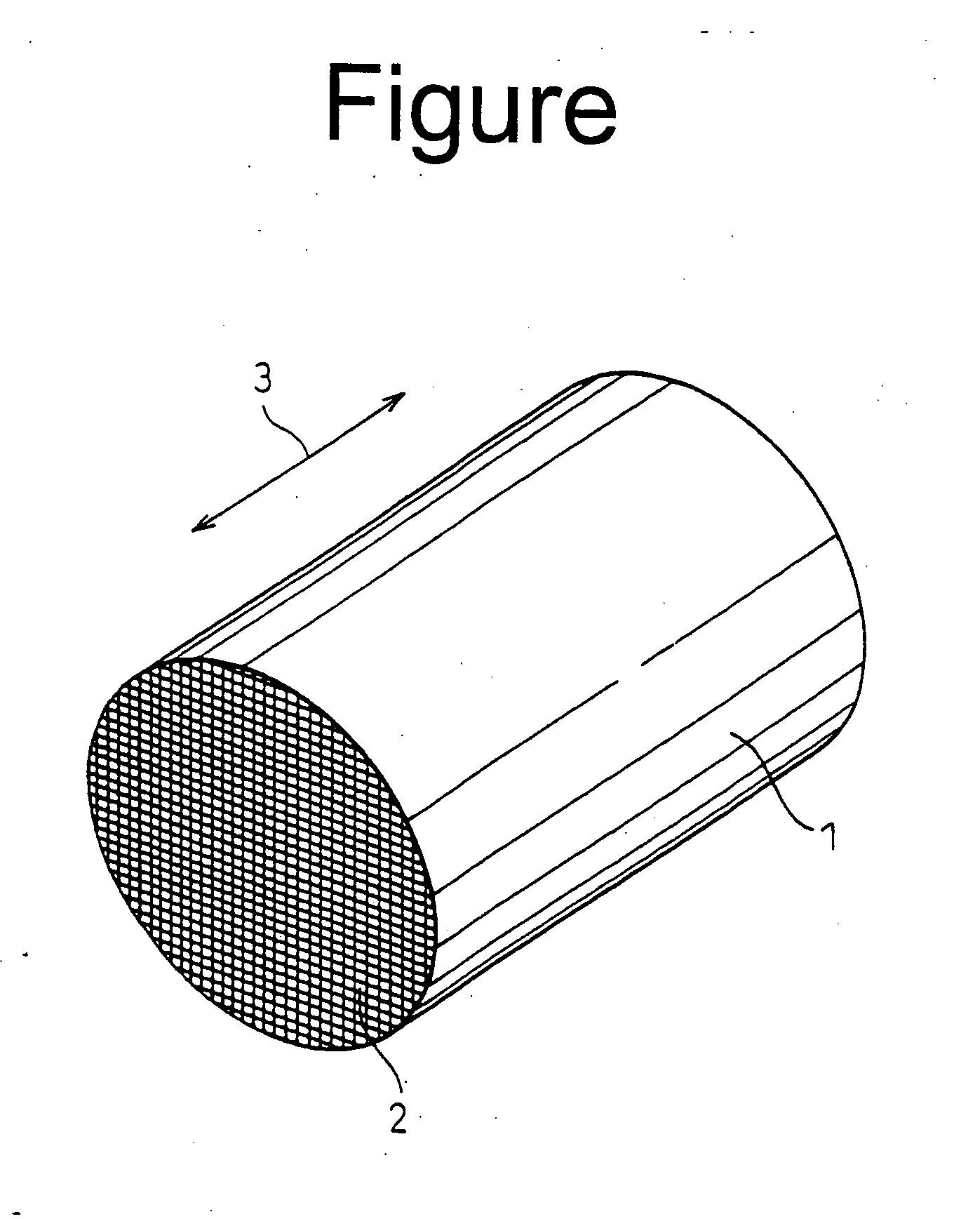
[0061] In Example 1, as the cordierite materials, talc, kaolin, alumina and aluminium hydroxide were used and formulated into a near theoretical cordierite composition. The cordierite materials were added with appropriate amounts of a binder, a lubricant and a humidicant, kneaded to a clay-like material and extruded to form a honeycomb shape having a cell wall thickness of 100 μm, a cell density of 400 cpsi (cells per square inch) and a diameter of 50 mm. The honeycomb shape was dried by heating, in air, up to 800° C. to remove the binder, and then fired by reducing the pressure to 6.7×10⁻⁴ Pa (5×10⁻⁶ Torr) and keeping the honeycomb shape under that pressure at 1390° C. for 2 hours, to obtain a honeycomb structure.

[0062] The obtained honeycomb structure was evaluated in the oxygen content of the honeycomb structure, the number of oxygen contained in the unit lattice of the cordierite crystal, the lattice constant of the b0 axis of the cordierite crystal, the amount of Pt supported ...

example 2

[0074] The same cordierite materials as in Example 1 was formed into a honeycomb shape, heated to remove a binder and then fired in a hydrogen atmosphere as a reducing atmosphere at 1390° C. for 2 hours.

[0075] The obtained honeycomb structure was evaluated in the same manner as in Example 1 and the results are also shown in Table 1.

[0076] It is clear from Table 1 that in comparison with Comparative Example 1, the cordierite honeycomb structure fired in a reducing atmosphere in Example 1 had a reduced content of the honeycomb structure, a reduced amount of oxygen contained in the unit lattice of the cordierite crystal, and a smaller lattice constant of the b0 axis of the cordierite crystal. It is therefore clear that oxygen left the cordierite crystals and oxygen vacancies were formed. When Pt was supported on the cordierite honeycomb structure, the amount of the Pt supported was 1.14 g / l in the case of water used as the solvent and 14.81 g / l in the case of ethanol used as the solv...

examples 6 to 10

[0086] In Examples 6 to 8, cordierite honeycomb structures were produced in the same manner as in Examples 3 to 5, except that the used firing atmosphere was a reduced pressure atmosphere having a pressure of 6.7 to 10−4 Pa (5×10⁻⁶ Torr).

[0087] In Examples 9 and 10, cordierite honeycomb structures were produced in the same manner as in Example 5, except that the used firing atmosphere was a hydrogen atmosphere as a reducing atmosphere.

[0088] The obtained cordierite honeycomb structures were evaluated in the same manner as in Example 1. The results are also shown in Table 2.

[0089] As seen in Table 2, in comparison with Comparative Examples 2 to 7, the cordierite honeycomb structures produced in Examples 6 to 10 had a reduced oxygen content of the honeycomb structure, a reduced number of the oxygen contained in the unit lattice of the cordierite crystal, and a smaller lattice constant of the b0 axis of the cordierite crystal. It is therefore clear that oxygen vacancies were formed....


PUM

PropertyMeasurementUnit
widthaaaaaaaaaa
average distanceaaaaaaaaaa
distanceaaaaaaaaaa

Abstract

A ceramic support capable of supporting a catalyst comprising a ceramic body having fine pores with a diameter or width up to 1000 times the ion diameter of a catalyst component to be supported on the surface of the ceramic body, the number of the fine pores being not less than 1×10¹¹ pores per liter, is produced by introducing oxygen vacancies or lattice defects in the cordierite crystal lattice or by applying a thermal shock to form fine cracks.

Description

[0001] This application is a Division of U.S. application Ser. No. 09 / 546,227, filed Apr. 10, 2000, pending, which claims priority to JP Application Nos. JP 11-102547, filed Apr. 9, 1999 and JP 2000-47467, filed Feb. 24, 2000. The entire contents of these applications are incorporated herein by reference.BACKGROUND OF THE INVENTION [0002] 1. Field of the Invention [0003] The present invention relates to a ceramic support for supporting a catalyst component for cleaning an exhaust gas from an internal combustion engine of an automobile, etc., a catalyst-ceramic body using the ceramic support, and processes for producing these. [0004] 2. Description of the Related Art [0005] A widely used conventional catalyst support for a catalyst component used to clean an exhaust gas is a honeycomb structure of cordierite, which is excellent in thermal shock resistance, the surface of which is coated with γ-alumina. This is because a cordierite honeycomb structure has a relatively small specific s...

Claims


Application Information

Patent Timeline
Patent Type & Authority Applications(United States)
IPC IPC(8): B01J23/00B01J21/14B01J35/04B01J37/00C04B35/195C04B38/00
CPCB01D53/944B01D2323/225B01D67/0041B01D71/024B01D71/025B01D2255/1021B01D2255/1025B01D2325/10B01J21/14B01J23/42B01J23/464B01J23/63B01J35/04B01J37/0009B01J37/0203C04B35/195C04B38/00C04B2111/0081C04B2201/00B01D63/066C04B35/64C04B38/0006C04B38/0054C04B41/00C04B41/0063
Inventor KOIKE, KAZUHIKONAKANISHI, TOMOHIKOUEDA, TAKESHITANAKA, MASAKAZU
Owner NIPPON SOKEN
Why Eureka
Try Eureka