Nonazeotropic terpineol-based spray suspensions for the deposition of electrolytes and electrodes and electrochemical cells including the same

a technology of terpineol and spray suspension, which is applied in the field of spray suspension, can solve the problems of high installation cost, high cost of evd process, and inability to meet cost targets for mass-market applications,

Inactive Publication Date: 2007-08-09
DAY MICHAEL J +1
View PDF7 Cites 34 Cited by
  • Summary
  • Abstract
  • Description
  • Claims
  • Application Information

AI Technical Summary

Benefits of technology

[0017]The present invention provides a spray suspension for electrolyte, cathode and anode material particles. The spray suspension allows aerosol deposition of green ceramic layers that subsequently can be sintered to produce both dense and porous ceramic layers. The suspensions and deposition approach allow formation of thin layers of varying microstructure and composition in the sintered state. The suspensions and deposition approach are likely to be useful in the fabrication of electrochemical systems, including but not limited to solid oxide fuel cells, solid oxide electrolyzers, ceramic oxygen generation systems, and ceramic membrane reactors.

Problems solved by technology

Such SOFC systems are expensive, with projected installed costs of $1500 / kW.
The EVD process is inherently expensive and unlikely to satisfy cost targets for mass-market applications.
Electrolyte deposition is a cell manufacturing step fraught with difficulty.
Electrochemical vapor deposition has an unparalleled ability to seal and grow YSZ layers of controlled thickness on any number of geometries but the cost of capital equipment required to scale this technique is prohibitive.
Tape-based and screen printing methods are most suited to planar geometries, which limit their usefulness in cold-end-seal (tubular) designs.
Efforts to reduce electrolyte thicknesses present a particular challenge with tape-based and screen printing methods because prevention of pinhole defects becomes more difficult.
The amounts of solvent required adversely affect the microstructure of the resulting coating, limiting the green density that can be obtained.
This results in lower system cost than EVD or other vapor or chemical based routes, although this cost is higher than that of aerosol spray methods.

Method used


Image

  • Nonazeotropic terpineol-based spray suspensions for the deposition of electrolytes and electrodes and electrochemical cells including the same
  • Nonazeotropic terpineol-based spray suspensions for the deposition of electrolytes and electrodes and electrochemical cells including the same
  • Nonazeotropic terpineol-based spray suspensions for the deposition of electrolytes and electrodes and electrochemical cells including the same

Examples


example 1

Preparation of Electrolyte Spray Suspension

[0058]In a 1 liter Nalgene bottle, 250 ml of 1 cm diameter zirconia media and 100 ml of acetone were added to 2.25 g Hypermer KD-1 dispersant. This material was placed on a vibratory mill for 10 minutes to completely dissolve the dispersant. To this solution, 150 g Daiichi ZrO2-6 mol % Sc2O3-1 mol % Al2O3 powder was added. The resultant slurry was returned to the vibratory mill for 24 hours to assure complete deagglomeration of the powder. The slurry was poured into a 1 liter Pyrex beaker and the solvent allowed to evaporate at 60° C. until half the initial volume of the slurry was reached. To this mixture, 80.85 g terpineol-based screen-printing vehicle (Johnson Matthey 63 / 2, medium grade) was added and stirring continued. When the slurry was again homogenized, the slow evaporation at 60° C. was resumed and continued until the specific gravity of the suspension reached 1.3 g / cm3. Small amounts of terpineol, a terpineol-based solvent or bin...

example 2

Preparation of Electrode Spray Suspension

[0059]In a 1 liter Nalgene bottle, 250 ml of 1 cm diameter zirconia media and 100 ml of acetone were added to 0.41 g Hypermer KD-1 dispersant. This material was placed on a vibratory mill for 10 minutes to completely dissolve the dispersant. To this solution, ˜125 g of cathode or anode composite powder was added. The resultant slurry was returned to the vibratory mill for 24 hours to assure complete deagglomeration of the powder. The slurry was poured into a Pyrex pan and the solvent allowed to evaporate in a convection oven held at 60° C. until dried. The powder was then sieved through a 60 mesh screen. 50 g powder was slowly added to 15 g terpineol-based screen printing vehicle (Johnson Matthey 63 / 2 medium) using an ultrasonic wand. The slurry was ultrasonicated for 15 minutes. Small amounts of terpineol, a terpineol-based solvent or binder system, or the majority solvent may be added to the prepared suspension as needed to reduce the suspe...

example 3

Electrolyte Deposition on Cathode Substrate

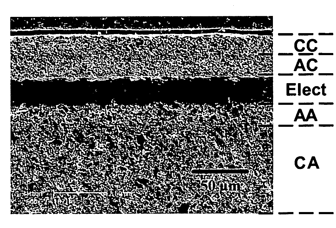
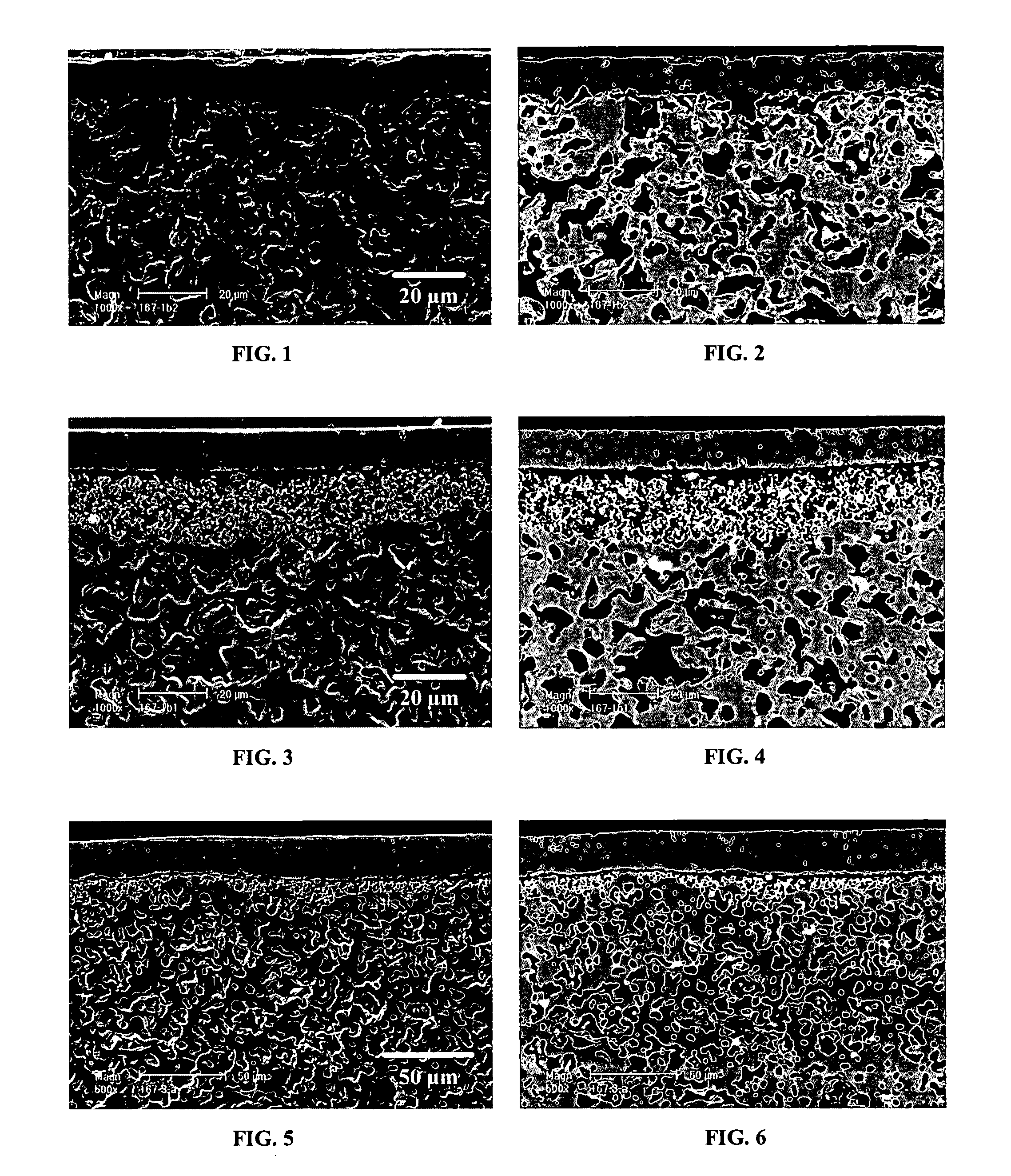
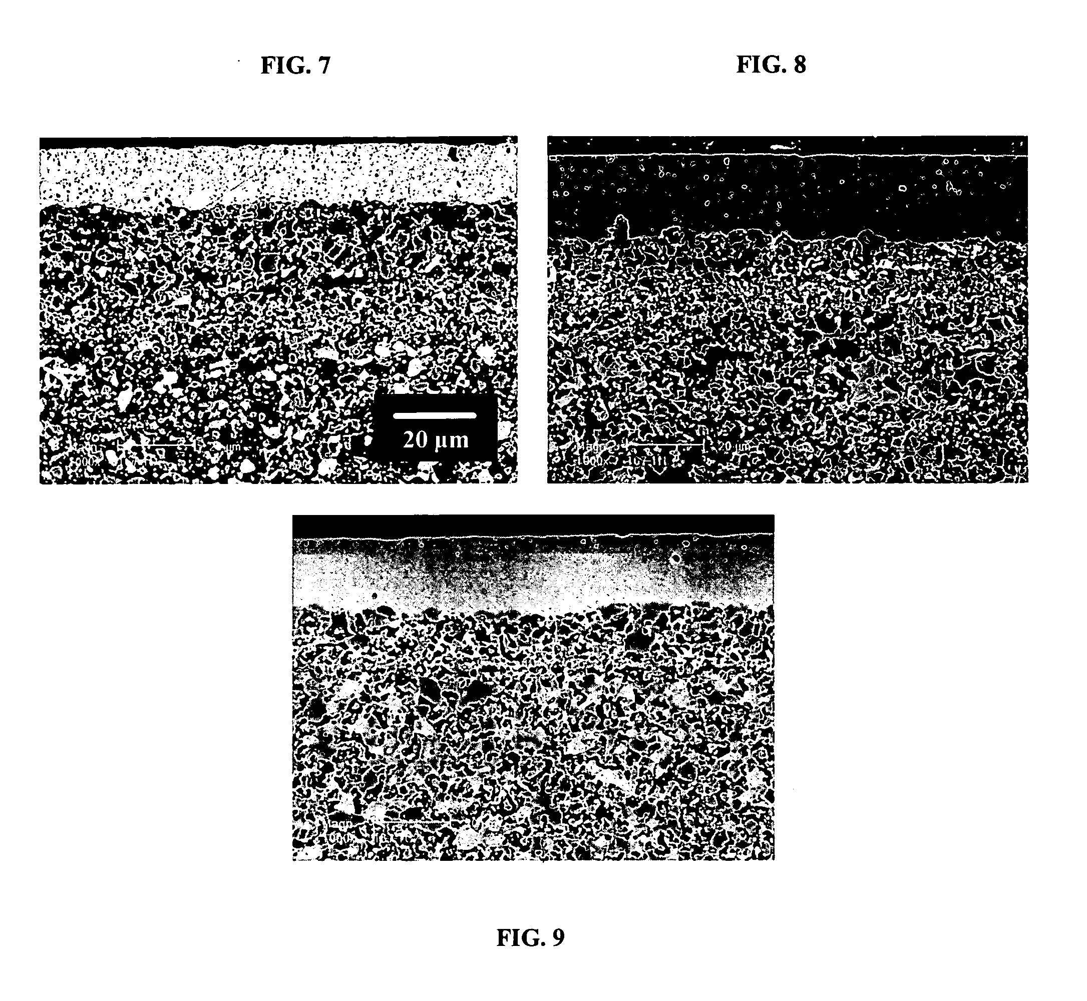
[0060]A coating of the electrolyte spray suspension was applied to a previously sintered lanthanum manganite-based cathode tube using a small airbrush. The electrolyte suspension as applied at a thickness sufficient to produce a coating 15 μm thick and then sintered at 1300° C. for one hour.

[0061]The resultant microstructure is shown in FIGS. 1 and 2. As can be seen in the micrographs, penetration of the film into the substrate was minimal due to the relatively high viscosity of the suspension.


PUM

PropertyMeasurementUnit
thicknessaaaaaaaaaa
temperaturesaaaaaaaaaa
diameteraaaaaaaaaa

Abstract

A family of spray suspensions for aerosol deposition of green ceramic layers that subsequently can be sintered to produce both dense and porous ceramic layers. The suspensions comprise a nonazeotropic solvent mixture, a ceramic powder, a dispersant, and a an organic binder. The invention also includes methods for depositing coatings of these ceramic suspensions on a substrate, either singly or sequentially, to form electrochemically efficient multilayer structures that can be economically co-sintered. The suspensions and deposition approach allow formation of thin layers of varying microstructure and composition in the sintered state. The suspensions and deposition approach are likely to be useful in the fabrication of electrochemical devices.

Description

STATEMENT REGARDING FEDERALLY SPONSORED RESEARCH[0001]This invention was made with government support under Contract No. DE-FG02-03ER83729 awarded by the United States Department of Energy. The United States Government has certain rights in this invention.CROSS-REFERENCE TO RELATED APPLICATIONS[0002]Not applicableREFERENCE TO MICROFICHE APPENDIX[0003]Not applicableFIELD OF THE INVENTION[0004]This invention relates to spray suspensions for aerosol deposition of ceramic materials. The suspensions and deposition approach may be useful in the fabrication of electrochemical devices.BACKGROUND OF THE INVENTION[0005]Solid oxide fuel cells (SOFCs) generate power using multilayer ceramic cells, each of which comprises porous anode, dense electrolyte, and porous cathode layers. Power generation in SOFCs involves the conversion of oxygen molecules (from air) to oxygen ions at the cathode, conductance of oxygen ions through the electrolyte, and reaction of these oxygen ions with fuel to form hy...

Claims


Application Information

Patent Timeline
Patent Type & Authority Applications(United States)
IPC IPC(8): H01M10/04C04B35/64B05D5/12
CPCC04B35/486Y10T29/49115C04B35/6264C04B35/62655C04B35/6365C04B41/009C04B41/52C04B41/89C04B2111/00853C04B2235/3217C04B2235/3224H01M4/9033H01M8/12H01M8/124H01M8/1253H01M8/126Y02E60/522Y02E60/525C04B35/6261C04B41/4543C04B41/5045C04B41/0072C04B41/5042C04B35/016C04B35/48C04B38/00Y02E60/50Y02P70/50
Inventor DAY, MICHAEL J.SEABAUGH, MATTHEW M.
Owner DAY MICHAEL J
Why Eureka
Try Eureka