
Method and apparatus for improved plasma arc torch cut quality

a plasma arc torch and cutting quality technology, applied in plasma welding apparatus, plasma technique, manufacturing tools, etc., can solve the problems of increasing reduce the entrainment of secondary gas, reduce the variation of the cut angle, and reduce the entrainment

Inactive Publication Date: 2007-08-09
HYPERTHERM INC
View PDF5 Cites 36 Cited by
  • Summary
  • Abstract
  • Description
  • Claims
  • Application Information

AI Technical Summary

Benefits of technology

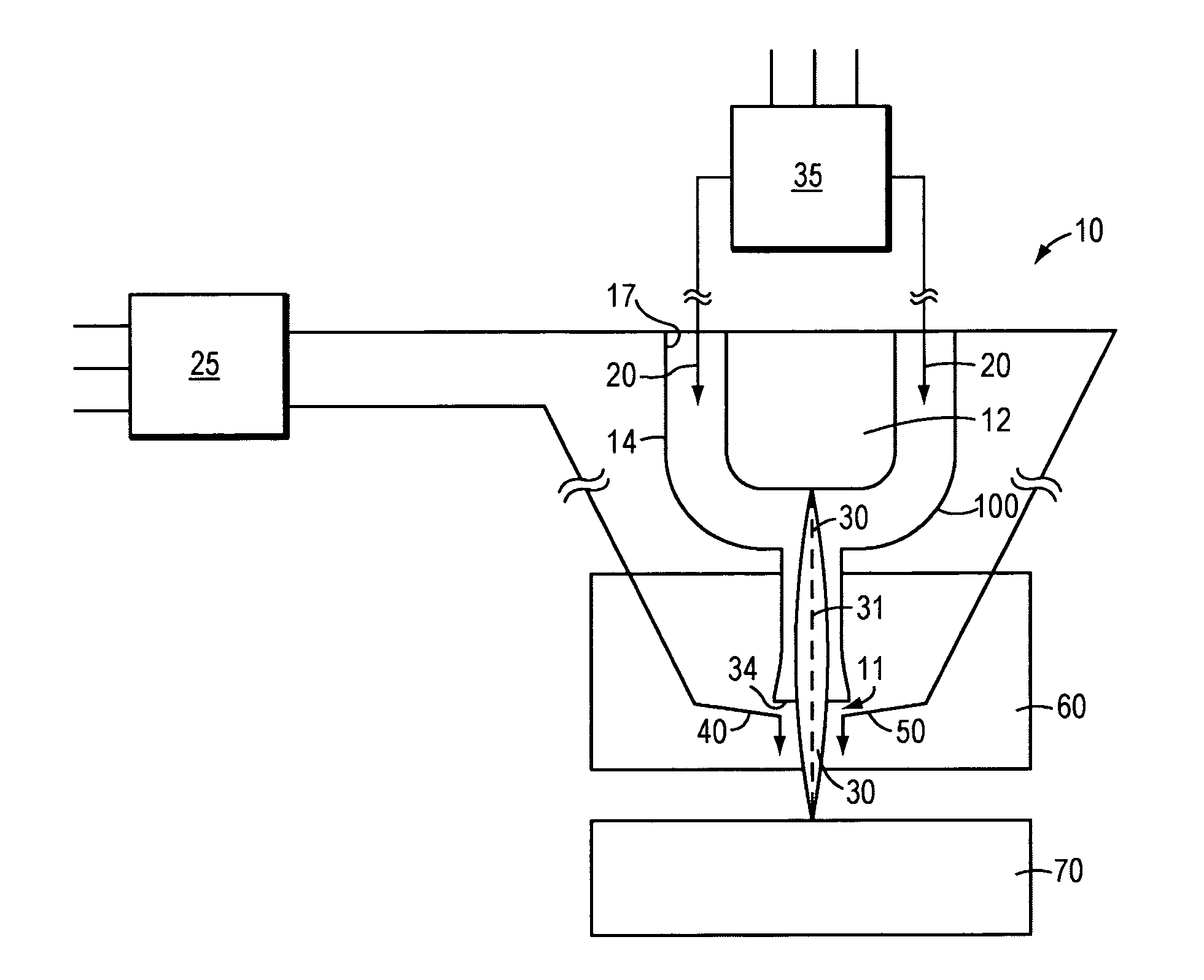
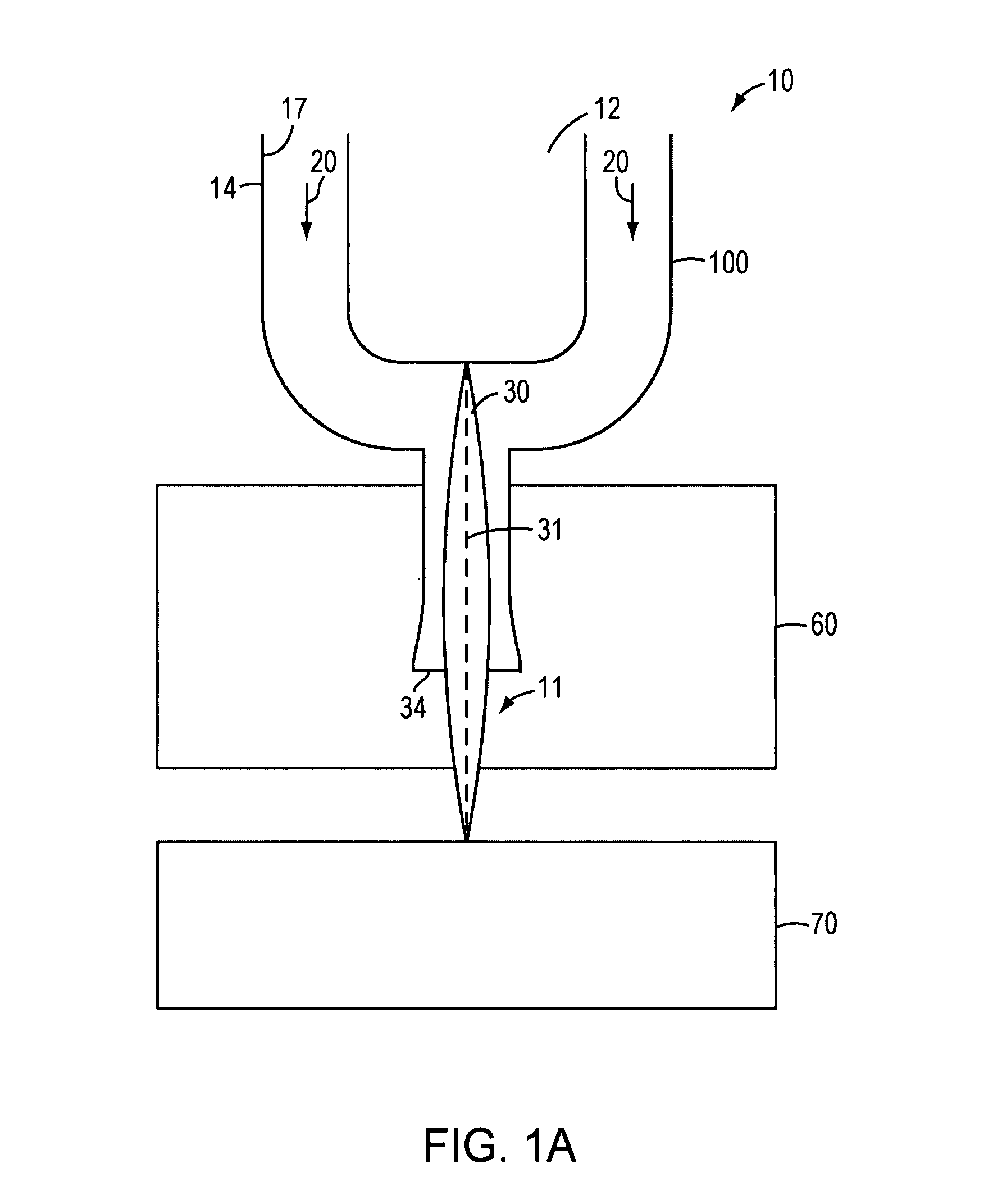
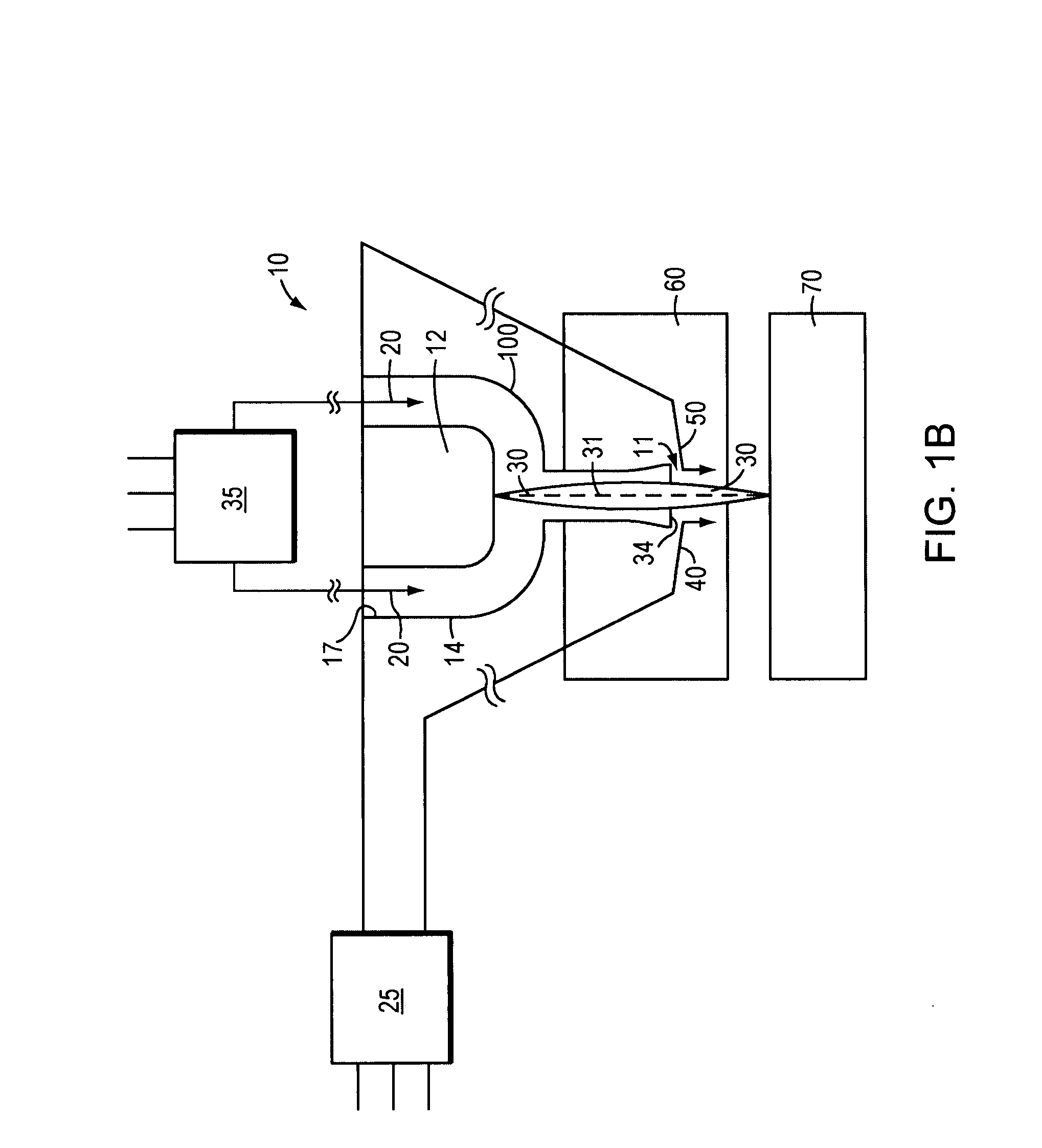
[0009] A controlled secondary gas density that reduces entrainment can reduce cut angle variation, thereby improving the plasma arc torch cut quality. Expected improvements in a material (e.g., a workpiece) cut according to the described methods and that employ the described plasma arc torches include one or more of reduction in surface roughness, reduction in top dross and reduction in top edge rounding. In addition, torches can be designed to direct the flow of the secondary gas through the secondary gas exit orifice at an orientation that reduces entrainment of the secondary gas into the plasma gas.
[0010] The invention relates to a plasma cutting torch, methods of operating a plasma (transferred) cutting arc, methods of controlling a secondary gas, and systems for cutting a material that reduce entrainment of the secondary gas flow with the plasma gas that forms the plasma arc thereby improving cutting performance. Generally, the flow of the secondary gas is controlled to reduce entrainment of the secondary gas into the plasma gas at, for example, a location external to a plasma exit orifice located at a first end of the plasma arc torch. The secondary gas can be controlled to provide a secondary gas density that reduces entrainment of the secondary gas into the plasma gas that forms that plasma arc. Generally, when in the cutting mode, the plasma cutting arc is a highly constricted, symmetrical, and stable plasma arc when it exits the nozzle.
[0011] For example, in one embodiment, controlling the density of the secondary gas includes controlling the density of the secondary gas flow to reduce the density differential between the plasma gas and the secondary gas in the region of the secondary gas exit orifice. In another embodiment, controlling includes controlling the density of the secondary gas flow to reduce the density differential between the plasma arc and the secondary gas flow when the secondary gas flow contacts the plasma arc. In another embodiment, a system for cutting a material includes a controller for controlling the density of the secondary gas flow to reduce the density differential between the plasma arc extending through a plasma exit orifice and the secondary gas flow when the secondary gas flow contacts the plasma arc.
[0012] In still another embodiment, the density of the secondary gas is controlled to provide a secondary gas density that minimizes entrainment of the secondary gas into the plasma gas. For example, the density of the secondary gas flow is controlled to minimize the density differential between the plasma gas and / or the plasma arc and the secondary gas flow.
[0013] Systems for cutting a material with a plasma arc torch can include a controller for controlling the density of the secondary gas flow to reduce the density differential between the plasma arc and the secondary gas flow when the secondary gas flow contacts the plasma arc. Suitable controllers can include, in one embodiment, a heater for controlling the temperature of the secondary gas flow. Controlling the temperature of the secondary gas with the heater can reduce entrainment between the secondary gas flow and the plasma arc. Temperature control of the secondary gas can be employed to reduce a density differential between the secondary gas flow and the plasma arc before the secondary gas flow contacts at least a portion of the plasma arc.
[0014] In another embodiment, the secondary gas is controlled to reduce the density difference between the plasma gas density and the secondary gas density. In one embodiment, the secondary gas density at ambient conditions is less than the density of Nitrogen gas at ambient conditions. For example, the secondary gas has a density at ambient conditions that is less than about 70% of the density of Nitrogen gas at ambient conditions. The secondary gas is, in one embodiment, a mixture of two or more gases, where, for example, the secondary gas includes at least 20% of an inert gas such as, for example, Helium. In another variation, the secondary gas is less than about 70% of an inert gas such as, for example, Helium.

Problems solved by technology

Recent research indicates that increased non-uniformity of secondary gas entrainment in a plasma arc leads to increased variation in cut angles.

Method used


Image

  • Method and apparatus for improved plasma arc torch cut quality
  • Method and apparatus for improved plasma arc torch cut quality
  • Method and apparatus for improved plasma arc torch cut quality

Examples


example 1

[0088] The experimental results demonstrate that introducing a secondary gas mixture including helium improves plasma arc torch cut quality. Cut quality is measured by surface roughness, top dross and top edge rounding, these measures are all reduced when the secondary gas includes helium and the secondary gas including helium flows at an angle that reduces entrainment of the secondary gas into the plasma arc.

[0089] Experiments were performed in which ⅜″ mild steel was cut using a plasma arc torch with various secondary gas mixtures of oxygen, nitrogen, argon, and helium. Plasma has a very low density and a high thermal conductivity. Both argon and helium are chemically inert gases that are not expected to chemically react with the surface of the workpiece. However, helium and argon have different density values, thermal conductivity values, and atomic weights. Helium has larger thermal conductivity and a lower density than argon. Specifically, Helium has a thermal conductivity of ...

example 2

[0099] In a second experiment, results demonstrate that introducing a secondary gas mixture including helium improves the quality of holes cut into mild steel by a plasma arc torch. Through holes cut into a metal material by a plasma arc torch can taper at one end of the through hole. Through holes are made in metal material to enable bolts to be secured to the material. Tapering in through holes causes issues including difficulty in cylinder / cutting clearance and issues in the field including difficulty affixing bolts through a through hole in a material. The thickness of the material through which a through hole is cut also impacts the through hole quality. Tapering in through holes is analogous to top edge rounding in an application where a substantially linear cut is being made. Imperfections in through hole quality is magnified where a through hole has a small diameter, because, for example, the impact of tapering can impact the usability of a through hole (for example, the abi...


PUM

PropertyMeasurementUnit
Fractionaaaaaaaaaa
Fractionaaaaaaaaaa
Fractionaaaaaaaaaa

Abstract

Controlling the flow of a secondary gas reduces entrainment of the secondary gas and a plasma gas that forms a plasma arc in a plasma arc torch system. Reducing entrainment of the secondary gas and the plasma gas that forms the plasma arc improves the quality of cuts made with the plasma arc torch.

Description

RELATED APPLICATION [0001] This application claims the benefit of and priority to and is a non-provisional application of the U.S. provisional patent application entitled “Method and Apparatus for Improved Plasma Arc Torch Cut Quality” filed on Jan. 27, 2006, U.S. Ser. No. 60 / 762,605, the entirety of which is incorporated by reference herein.FIELD OF THE INVENTION [0002] The invention generally relates to the field of plasma arc torch systems and processes. In particular, the invention relates to plasma arc torch systems, operation methods, systems for cutting a material, and methods of controlling a secondary gas in a plasma arc torch. BACKGROUND OF THE INVENTION [0003] Plasma arc torches are widely used in the cutting or marking of metallic materials. Generally, an electrode is mounted in a plasma torch, a nozzle with a central exit orifice is mounted within the torch body, the torch includes electrical connections, passages for cooling, arc control fluids, and a power supply. In ...

Claims


Application Information

Patent Timeline
IPC IPC(8): B23K9/00
CPCB23K10/00B23K10/006H05H1/34H05H2001/3494H05H1/341H05H2001/3478H05H1/3405H05H1/3478H05H1/3494
Inventor LINDSAY, JON W.
Owner HYPERTHERM INC
Learn More