Compact laser spectrometer

a compact, laser technology, applied in the direction of optical radiation measurement, instruments, spectrometry/spectrophotometry/monochromators, etc., can solve the problems of bulky and complex system with slow measurement time, weak signal to noise ratio of filtered white light source, and limited application range of prior-art white light spectrometer of fig. 1 , to achieve the effect of wide wavelength range, high speed modulation, and fast measurement tim

Inactive Publication Date: 2007-08-09
JAYARAMAN VIJAYSEKHAR
View PDF7 Cites 23 Cited by
  • Summary
  • Abstract
  • Description
  • Claims
  • Application Information

AI Technical Summary

Benefits of technology

[0012] The present invention provides a plurality of semiconductor lasers comprising a plurality of semiconductor gain medium compositions clustered over a spatial extent that is small compared to a minimum feature size of a sample being probed. These semiconductor lasers can be arranged in a linear array or two-dimensional array. An output radiation of the semiconductor laser cluster is preferab

Problems solved by technology

Although it enables spectral measurements over a wide wavelength coverage, the prior-art white light spectrometer of FIG. 1 suffers from a number of limitations.
First, the filtered white light source has weak signal to noise ratio.
Second, the grating-based system has critical intra-system mechanical alignments, and contains moving parts, leading to a bulky and complex system with slow measurement times. Lastly, some applications, such as (B. Tromberg, N. Shah, R. Lanning, A. Cerussi, J. Espinoza, T. Pham, L. Svaasand, and J. Butler, “Non-Invasive In Vivo Characterization of Breast Tumors Using Photon Migration Spectroscopy,”Neoplasia, vol.
26-40) employ frequency doma

Method used


Image

  • Compact laser spectrometer
  • Compact laser spectrometer
  • Compact laser spectrometer

Examples


Embodiment Construction

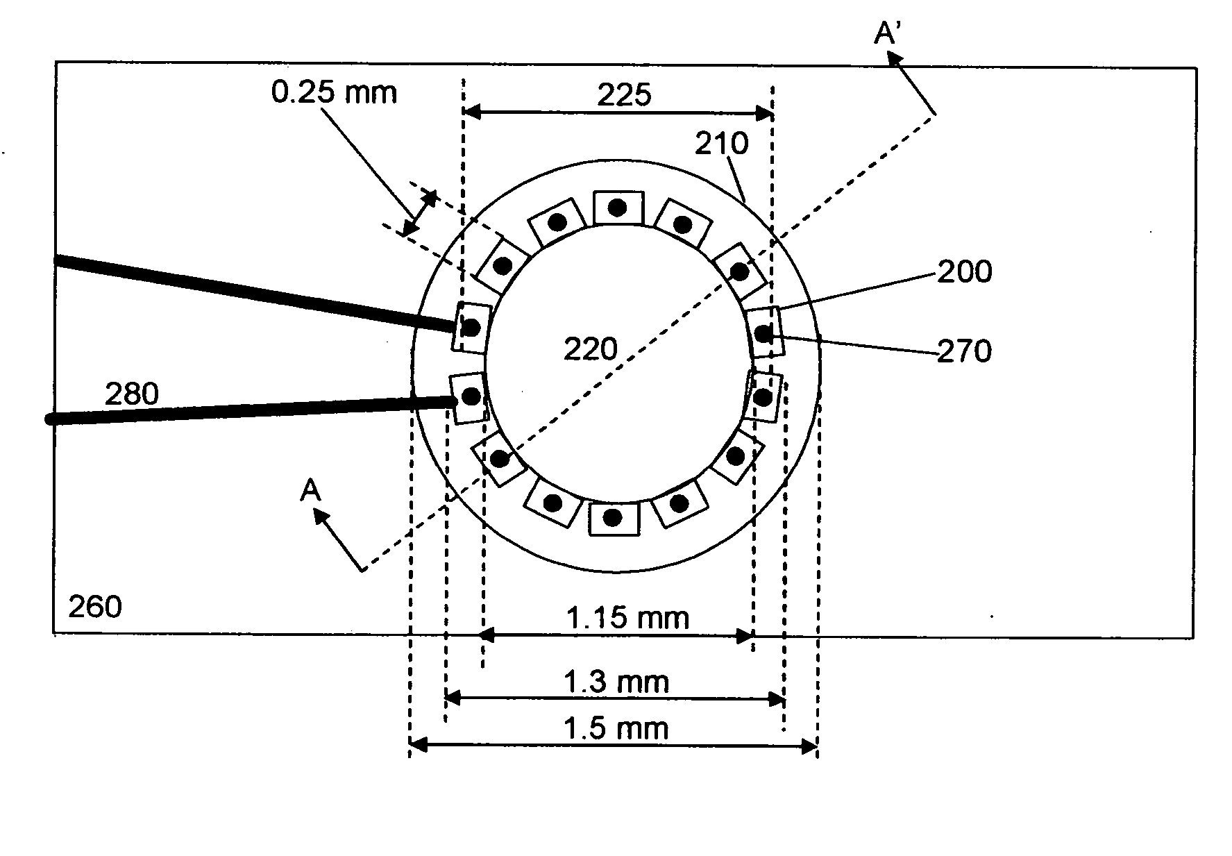
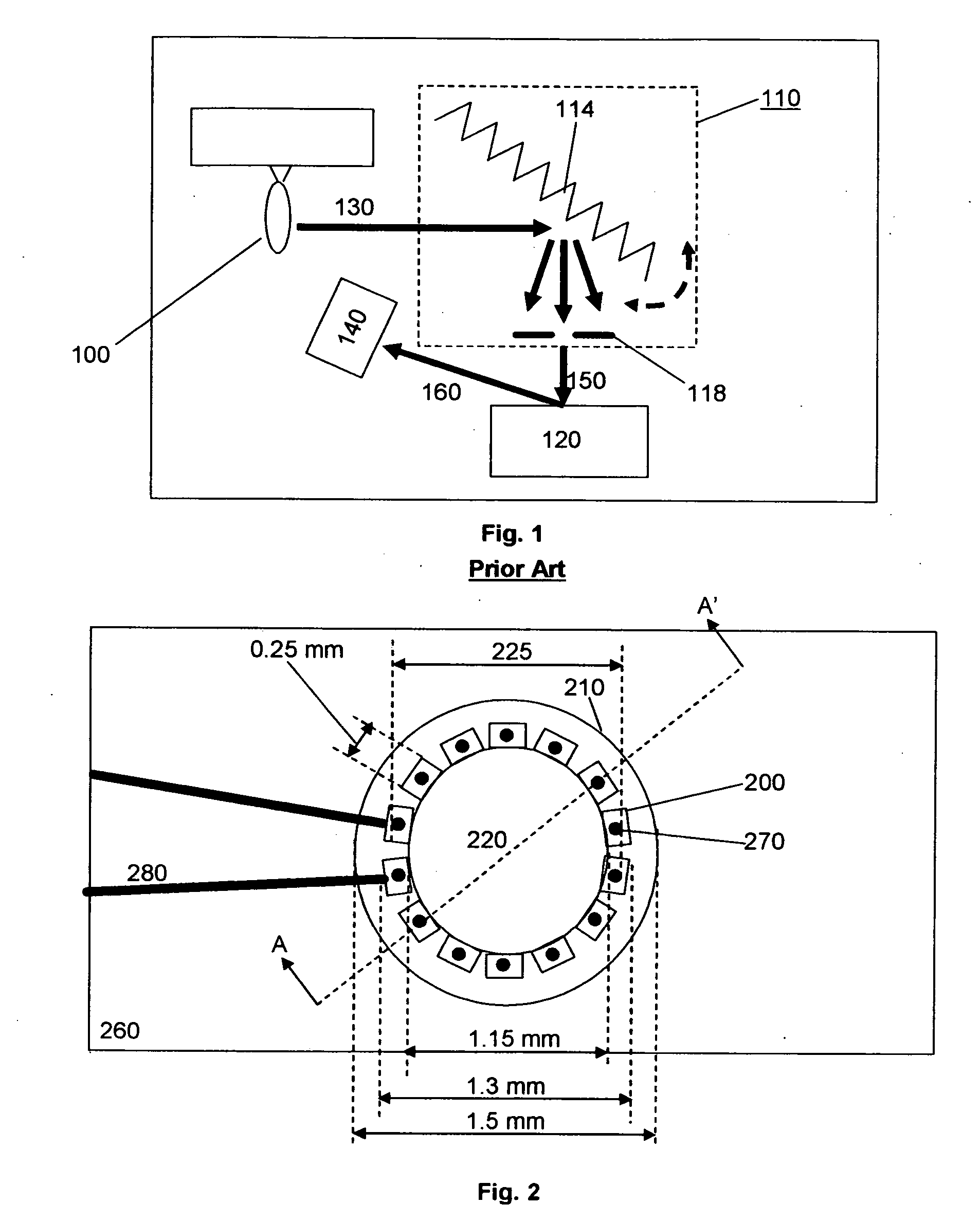
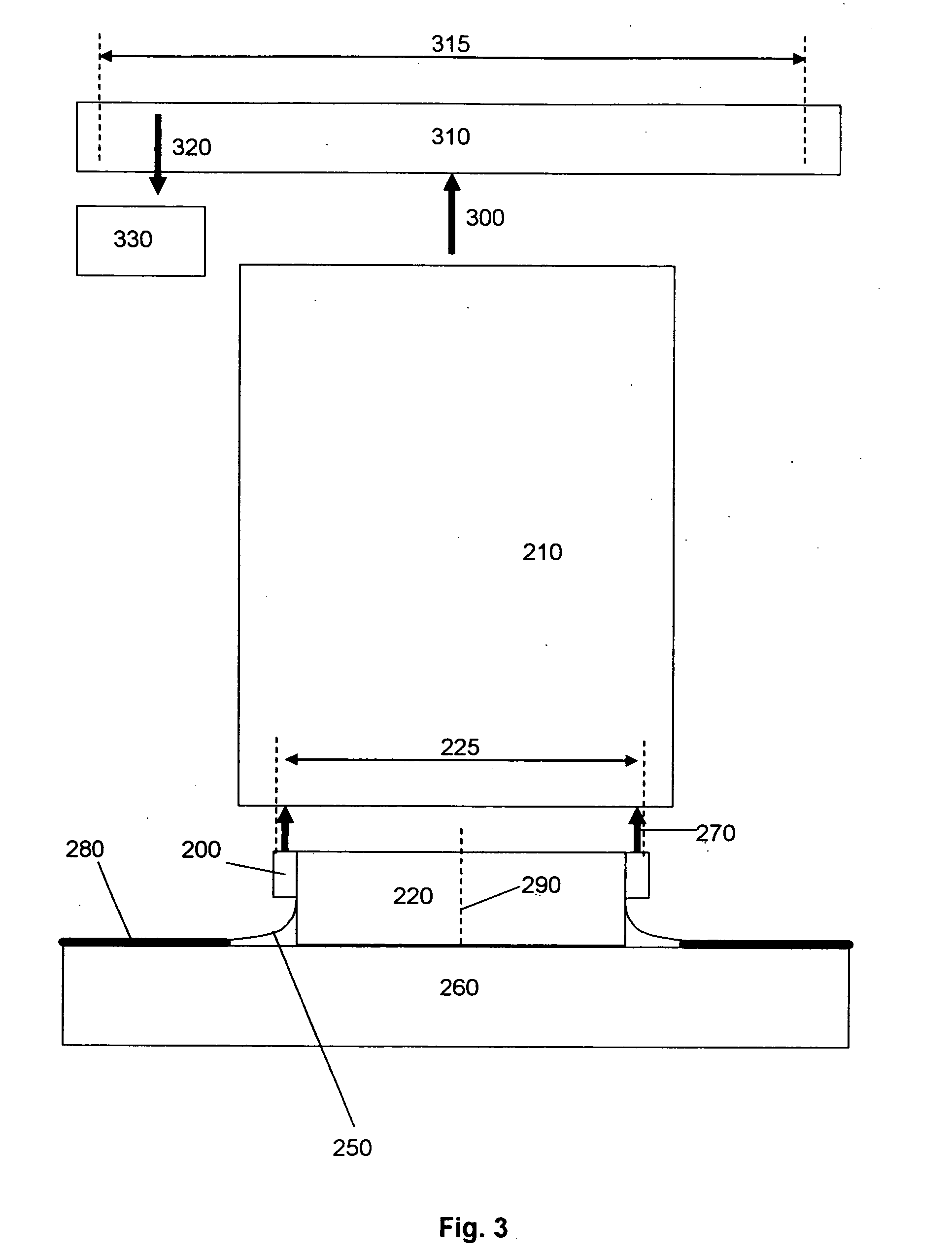
[0055]FIGS. 2 and 3 represent two views of a preferred embodiment of the present invention. FIG. 2 is an end view of a preferred embodiment of the present invention. The view of FIG. 2 is looking from the inside of a multi-mode optical fiber core 210 at a plurality of edge-emitting semiconductor lasers 200 arranged around the perimeter of a common circular cross-section cylindrical sub-carrier 220, fitting within the core of the multi-mode optical fiber 210. A plurality of radiation components 270 originates from an area having a maximum transverse dimension 225. Throughout this specification, whenever we refer to light “originating from” a location, we refer to the location at which the light first exits semiconductor, typically the output facet of a semiconductor laser diode. The configuration of FIG. 2 is in contrast to the configuration of (B. Tromberg, N. Shah, R. Lanning, A. Cerussi, J. Espinoza, T. Pham, L. Svaasand, and J. Butler, “Non-Invasive In Vivo Characterization of Br...


PUM


Abstract

A compact laser spectrometer according to the present invention includes a plurality of semiconductor lasers comprising a plurality of semiconductor gain medium compositions emitting a plurality of radiation components originating from an area having a maximum transverse dimension that is smaller than a minimum feature size of a sample. A broadband optical detector detects a diffuse reflectance. In one preferred embodiment of this invention the plurality of semiconductor lasers consists of Fabry-Perot edge-emitting lasers arranged around the perimeter of a cylindrical submount with a substantially circular cross-section. The plurality of radiation components is directly coupled to a multi-mode optical fiber, which presents radiation to a sample. In another preferred embodiment a linear array of Fabry-Perot edge-emitting lasers is directly coupled to a multi-mode fiber. In still another preferred embodiment, a two-dimensional array of vertical cavity surface-emitting lasers is directly coupled to a multi-mode optical fiber.

Description

CROSS-REFERENCES TO RELATED APPLICATIONS [0001] This application is entitled to the benefit of Provisional Patent Application Ser. No. 60 / 760,619, filed 2006, Jan. 20.STATEMENT REGARDING FEDERALLY SPONSORED RESEARCH OR DEVELOPMENT [0002] This invention was made under a government grant. The U.S. government may have rights in this invention.BACKGROUND [0003] 1. Field of the Invention [0004] This invention relates generally to tunable sources, spectroscopy, and multi-wavelength laser arrays. [0005] 2. Description of Prior Art [0006] Spectroscopy refers to the use of multi-wavelength radiation to non-invasively probe a variety of samples to determine the composition, health, or function of those samples. Prior-art spectroscopy is done with filtered white light sources, as illustrated in the prior art FIG. 1. Here, a white light source 100 emits a broadband radiation 130, which is filtered with a tunable monochromator 110, comprising a rotating grating 114 and slit 118, to generate a na...

Claims


Application Information

Patent Timeline
IPC IPC(8): G01J3/00G01J3/30
CPCG01J3/108
Inventor JAYARAMAN, VIJAYSEKHAR
Owner JAYARAMAN VIJAYSEKHAR
Why Eureka
Try Eureka